Downhole determination of drilling state

a technology of drilling state and downhole, applied in the field of downhole processing of drilling measurements, can solve the problems of consuming valuable rig time and requiring sufficient bandwidth, and achieve the effects of reducing dangerous dynamic conditions, improving drilling performance, and saving valuable rig tim

Active Publication Date: 2014-05-08
SCHLUMBERGER TECH CORP
View PDF1 Cites 56 Cited by
  • Summary
  • Abstract
  • Description
  • Claims
  • Application Information

AI Technical Summary

Benefits of technology

[0007]The disclosed embodiments may provide various technical advantages. For example, the disclosed embodiments enable the drilling state to be determined downhole without any surface communication or intervention. The drilling state may be used by a downhole controller (or controllers) to automatically direct various components of the BHA thereby saving valuable rig time. The disclosed embodiments also enable one or more components of the dynamic drilling energy of the BHA to be computed downhole. The computed energy may be used to improve drilling performance and mitigate dangerous dynamic conditions (such as bit bounce, stick slip, lateral vibrations, and bit whirl).

Problems solved by technology

However, downhole tools are generally disconnected from the surface and are therefore “unaware” of the drilling state.
While the drilling state may be transmitted from the surface to the bottom hole assembly (BHA), such transmission requires sufficient bandwidth and consumes valuable rig time (especially if a transmission is required after each change to the drilling state).

Method used


Image

  • Downhole determination of drilling state
  • Downhole determination of drilling state
  • Downhole determination of drilling state

Examples


embodiment 100

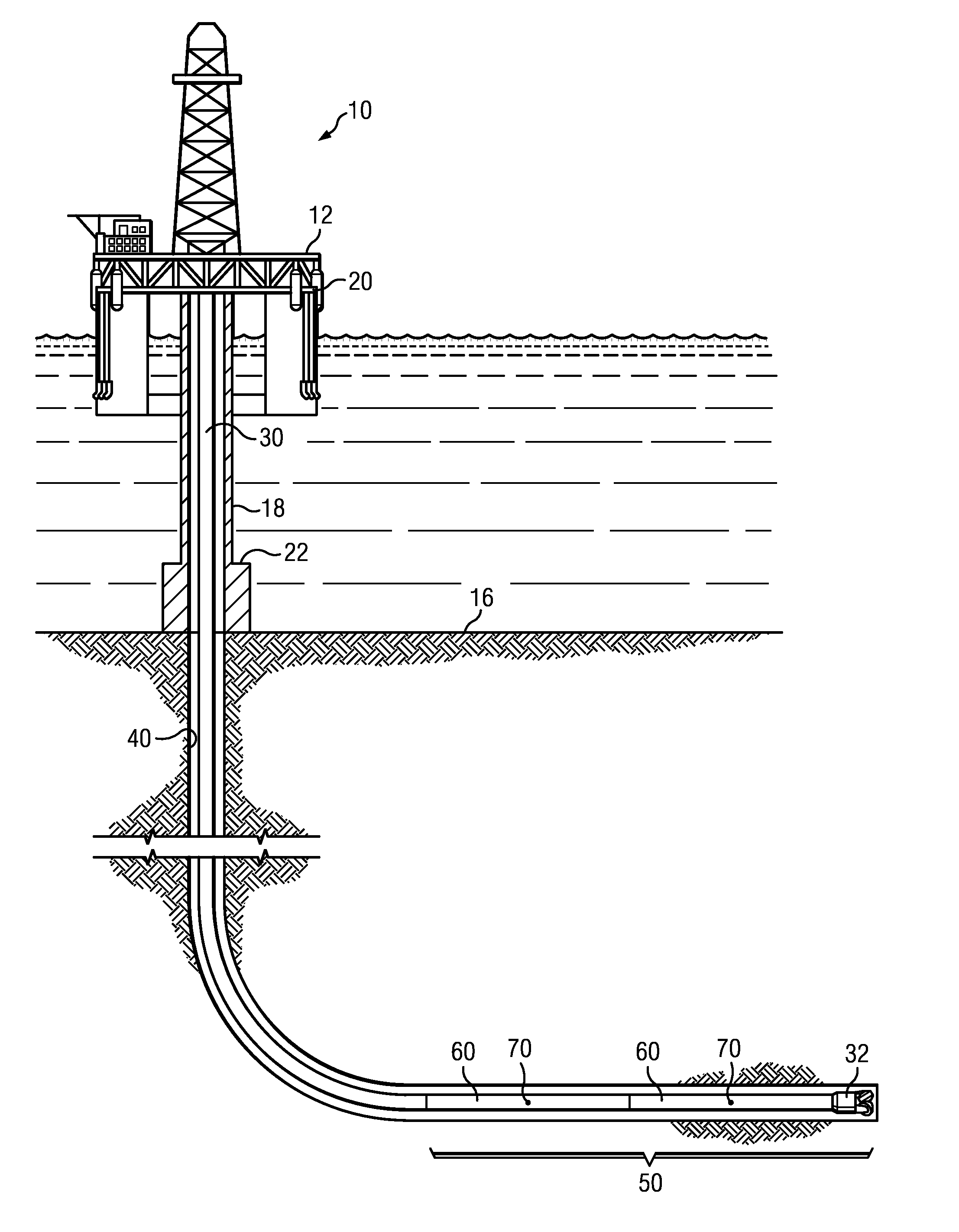
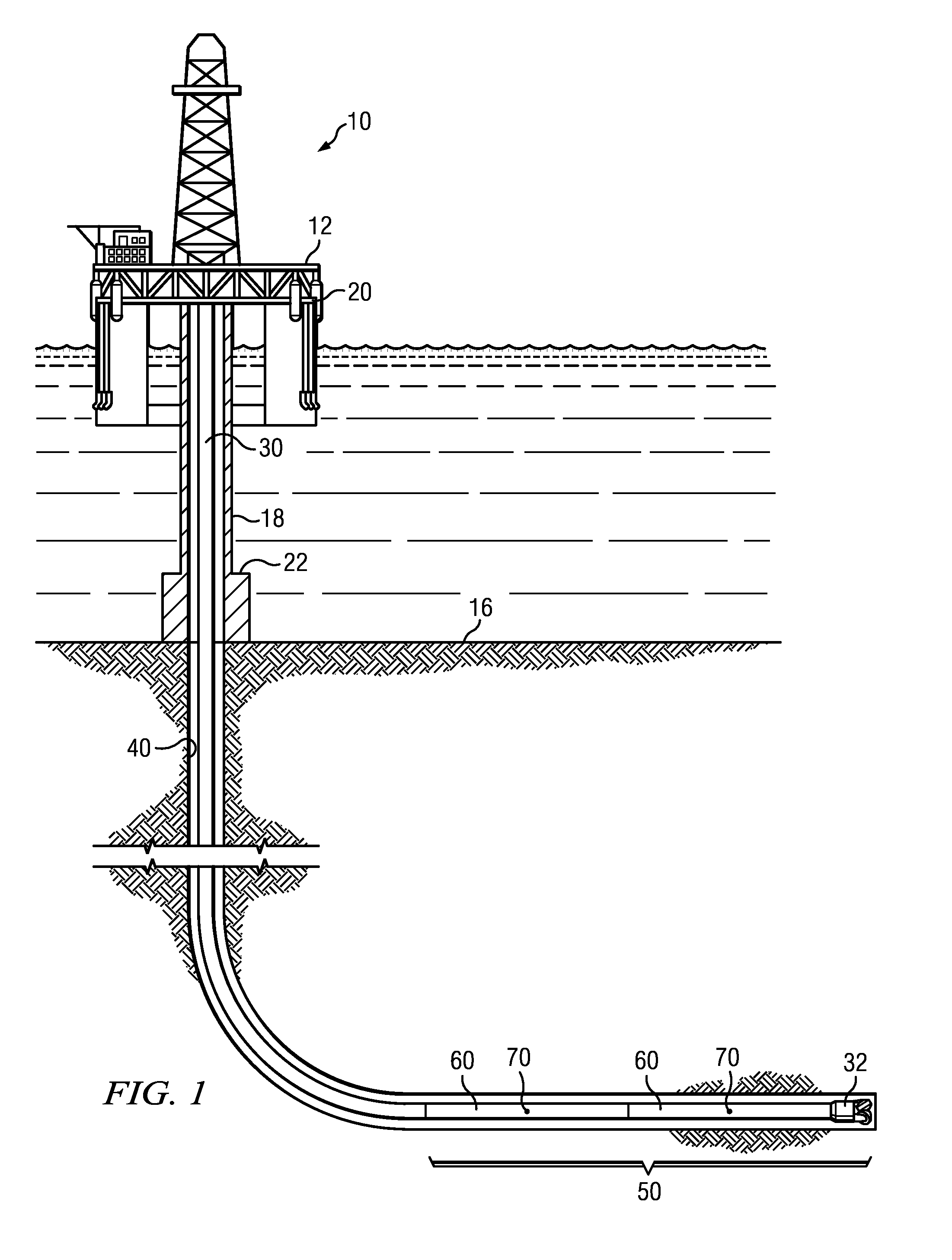
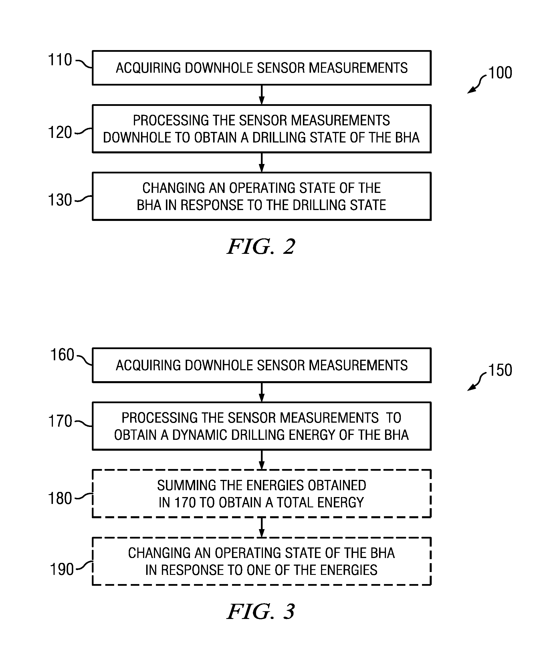
[0017]FIG. 2 depicts a flow chart of one disclosed method embodiment 100 for making a downhole determination of the drilling state. The method 100 includes acquiring (at 110) one or more downhole measurements of the BHA, the borehole, and / or the subterranean formation using downhole sensor(s) 70. The sensor measurements may be processed alone or in combination downhole at 120 using a downhole processor to determine the drilling state of the BHA. An operating state of one of the sensors and / or downhole tools 60 in the BHA 50 may then be changed at 130 in response to the drilling state determined at 120.

[0018]As stated above, the sensor measurements may include measurements of the BHA, the borehole, and / or the subterranean formation through which the borehole is being drilled. The sensor measurements may be indicative, for example, of drilling mechanics, drilling dynamics, the direction of drilling (the borehole azimuth and inclination), the size and shape of the borehole, and various...

embodiment 150

[0028]FIG. 3 depicts a flow chart of one disclosed method embodiment 150 for computing the dynamic drilling energy of a bottom hole assembly. The method includes acquiring at least one sensor measurement (e.g., accelerometer and / or strain gauge measurements) from corresponding sensors deployed in the bottom hole assembly at 160. A downhole processor processes the sensor measurements at 170 to obtain at least one of (i) an energy of axial motion of the bottom hole assembly, (ii) an energy of rotational motion of the bottom hole assembly, and (iii) an energy of lateral motion of the bottom hole assembly. These energies may further optionally be summed at 180 to obtain a total energy per unit length of the bottom hole assembly. The method may further optionally include automatically changing an operating state of at least one component of the bottom hole assembly at 190 in response one or more of the computed energies. It will be understood that in detecting severe events (such as the ...


PUM


Abstract

A method for determining a drilling state of a bottom hole assembly in a wellbore includes acquiring one or more downhole sensor measurements and processing the sensor measurements using a downhole processor to determine a drilling state of the bottom hole assembly. An operating state of the bottom hole assembly may be automatically changed in response to the determined drilling state. A method for computing a dynamic drilling energy of a bottom hole assembly includes acquiring at least one sensor measurement and processing the sensor measurements to obtain at least one of (i) an energy of axial motion of the bottom hole assembly, (ii) an energy of rotational motion of the bottom hole assembly, and (iii) an energy of lateral motion of the bottom hole assembly.

Description

CROSS REFERENCE TO RELATED APPLICATIONS[0001]This application claims the benefit of U.S. Provisional Application Ser. No. 61 / 723,740 entitled Determining Drill State of Bottom Hole Assembly, filed Nov. 7, 2012 and U.S. Provisional Application Ser. No. 61 / 724,681 entitled Drilling Dynamic Energy Estimation, filed Nov. 9, 2012.FIELD OF THE INVENTION[0002]Disclosed embodiments relate generally to methods for downhole processing of drilling measurements and more particularly to a method for downhole processing of drilling measurements to obtain a drilling state such as a dynamic drilling energy of a bottom hole assembly while drilling.BACKGROUND INFORMATION[0003]The use of automated drilling methods is becoming increasing common in drilling subterranean wellbores. Such methods may be employed, for example, to control the speed and / or the direction of drilling. Automated methods may also be employed during measurement while drilling (MWD) or logging while drilling (LWD) operations to col...

Claims


Application Information

Patent Timeline
Patent Type & Authority Applications(United States)
IPC IPC(8): E21B47/024
CPCE21B47/024E21B44/005
Inventor HARMER, RICHARDALDRED, WALTER DAVIDJEFFRYES, BENJAMIN
Owner SCHLUMBERGER TECH CORP
Why Eureka
Try Eureka