
Intelligent valve network

a valve network and intelligent technology, applied in water supply installation, process and machine control, instruments, etc., can solve the problems of large environmental damage, affecting the environment, and huge losses for companies

Inactive Publication Date: 2014-05-15
MARINEZ LUIS
View PDF5 Cites 64 Cited by
  • Summary
  • Abstract
  • Description
  • Claims
  • Application Information

AI Technical Summary

Benefits of technology

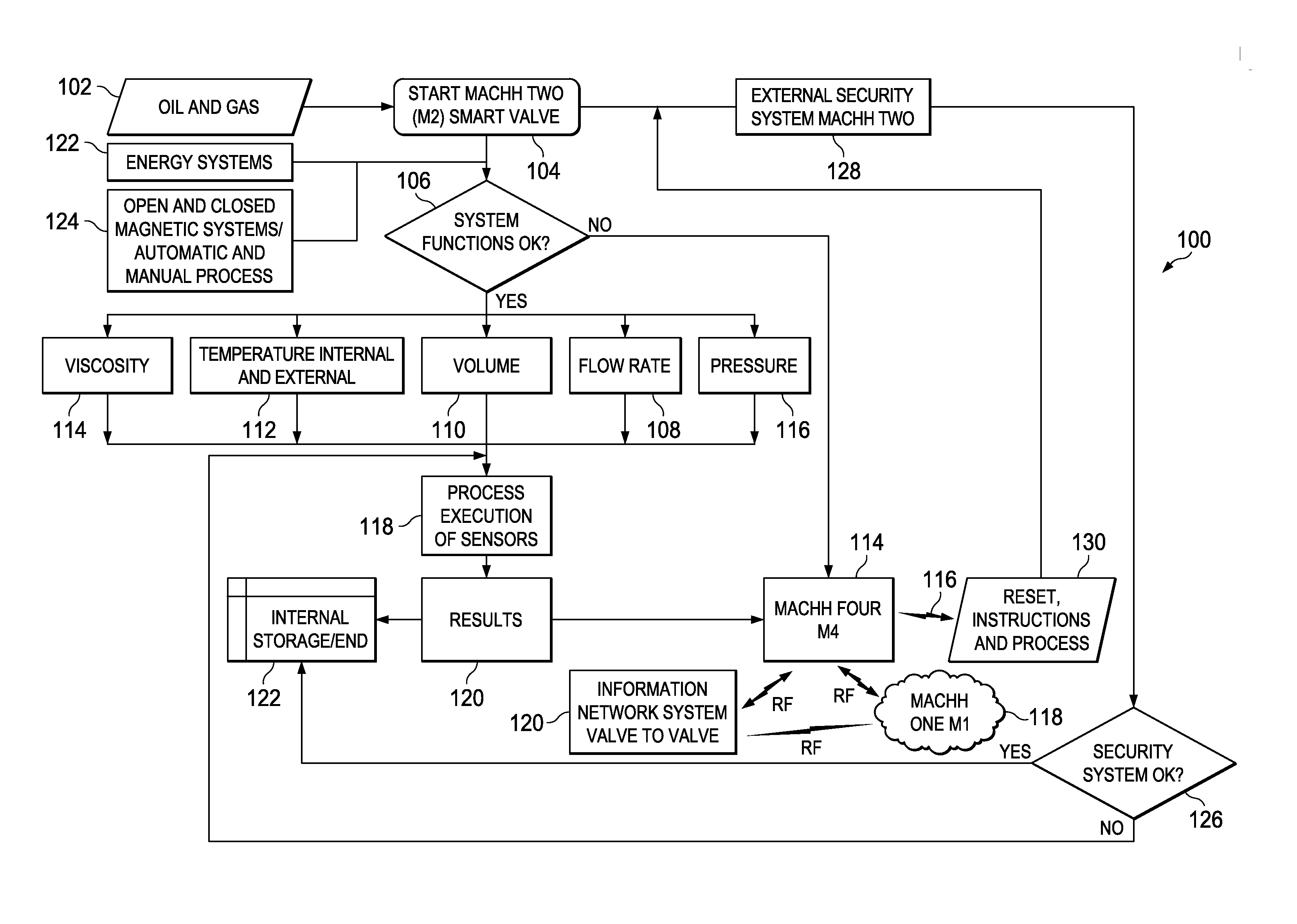
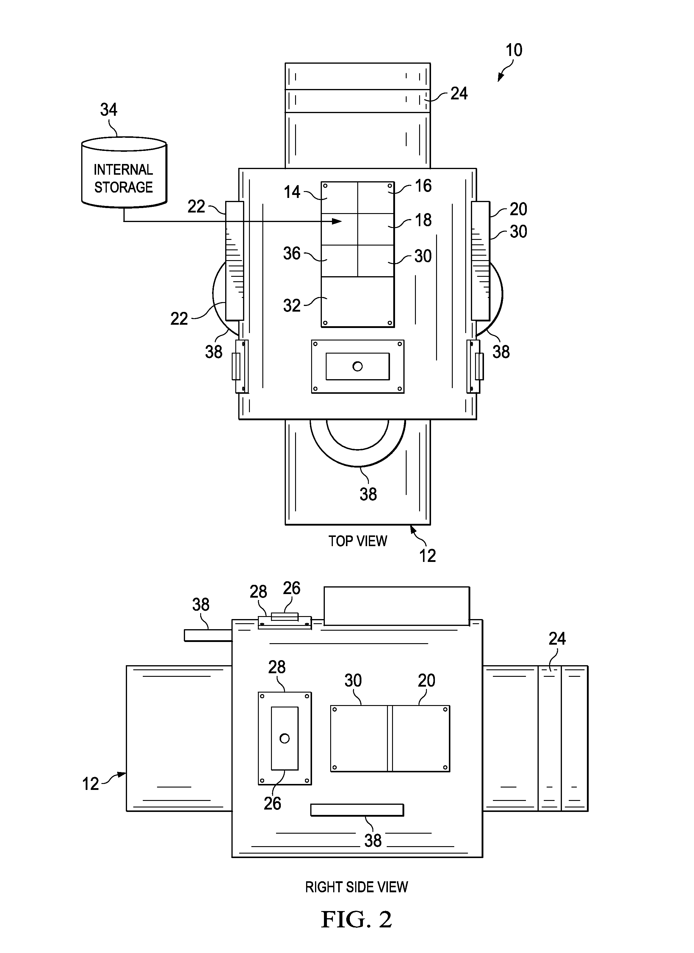
The present invention is a valve network that includes multiple valves connected to a communication network. Each valve has a sensor to detect pressure, flow, viscosity, and temperature, and an electrical power generator to generate power from the fluid flow. A processor controls the position of the valve based on the sensor data and can communicate with other valves or a control unit. A security module can also be included to send information about the status of the fluid flow. The valves can be actuated mechanically, electrically, or by other means such as a battery or fuel cell. The invention allows for synchronized opening, partially opening, and closing of valves based on parameters related to fluid flow through the valves. The valve network can be used in a pipeline and data can be shared across valves or valves of the pipeline.

Problems solved by technology

Despite numerous developments around process automation in a valve (aperture and closure of liquid or gas flow) widespread problems continue with pipelines of oil and its derivatives, including explosions, spills of products (in the case of oil and gasoline) and many problems affecting the environment and generate huge losses to companies.
Vandalism is another problem associated with large pipelines, which is very common in all countries.
Vandalism often causes great environmental damage around pipelines and also leads to losses from lack of productivity and increased operational costs.
Furthermore, thieves often penetrate the pipelines, stealing the product (oil, diesel or gasoline) and for the pressure and / or volume, and injected water to hide the loss in flow.
Presently, there is no way to determine in these conditions when the product is being lost.
Another problem in the operation of pipelines is the lack of process automation in the energy field.
Current processes for automating oil pipelines include limitations from the power supply for mechanically opening and closing the valves, as these often requires a lot of horsepower to close the flow of material (oil, gasoline) in the mechanism such as disk valves, ball valves, butterfly valves, slips valves, or any other system.
On the other hand, the process for transmitting of data and operation mechanisms are similarly limited due to poor coverage in some areas where remote GPRS signals are transmitted through the pipelines.

Method used


Image

  • Intelligent valve network
  • Intelligent valve network
  • Intelligent valve network

Examples


Embodiment Construction

[0033]While the making and using of various embodiments of the present invention are discussed in detail below, it should be appreciated that the present invention provides many applicable inventive concepts that can be embodied in a wide variety of specific contexts. The specific embodiments discussed herein are merely illustrative of specific ways to make and use the invention and do not delimit the scope of the invention.

[0034]To facilitate the understanding of this invention, a number of terms are defined below. Terms defined herein have meanings as commonly understood by a person of ordinary skill in the areas relevant to the present invention. Terms such as “a”, “an” and “the” are not intended to refer to only a singular entity, but include the general class of which a specific example may be used for illustration. The terminology herein is used to describe specific embodiments of the invention, but their usage does not delimit the invention, except as outlined in the claims.

[...


PUM


Abstract

The present invention includes a valve for connecting to a valve network comprising: at least one valve assemble, having at least one valve to control a fluid or gas flow through an opening in the valve assembly; at least one pressure sensor; viscosity sensor; flow rate detector; and temperature sensor; at least one processor connected to each of the valve and sensors, wherein the processor is capable of controlling the position of the valve based on the information obtained from the sensors; at least one communications module connected to the processor capable of transmitting to and receiving information from the valve network and capable of sending information obtained from the valve assembly to the valve network of the status of the fluid or gas flowing through the valve assembly; and at least one power source that provides power to the valve assembly.

Description

CROSS-REFERENCE TO RELATED APPLICATIONS[0001]This application claims priority to U.S. Provisional Application Ser. No. 61 / 712,696, filed Oct. 11, 2012, the entire contents of which are incorporated herein by reference.TECHNICAL FIELD OF THE INVENTION[0002]The present invention relates in general to the field of delivery of fluids via pipelines, and more particularly, to an intelligent valve network that controls all aspects of fluid flow within a pipeline including preprogrammed control routines and intelligent control decisions via software and hardware.STATEMENT OF FEDERALLY FUNDED RESEARCH[0003]None.BACKGROUND OF THE INVENTION[0004]Without limiting the scope of the invention, its background is described in connection with valve control.[0005]One such system is taught in U.S. Pat. No. 8,127,783, issued to Balarabe, et al., which teaches a method for preventing a mass flow controller from participating in cross-talk in an array of mass flow controllers. The method includes sensing ...

Claims


Application Information

Patent Timeline
Patent Type & Authority Applications(United States)
IPC IPC(8): G05D7/06
CPCG05D7/0617F16K37/005Y10T137/7761Y10T137/0324F17D3/01F17D1/20F17D5/00
Inventor MARINEZ, LUIS
Owner MARINEZ LUIS
Features
  • Generate Ideas
  • Intellectual Property
  • Life Sciences
  • Materials
  • Tech Scout
  • Unparalleled Data Quality
  • Higher Quality Content
  • 60% Fewer Hallucinations
Learn More