Controllable electrical receptacle with routed antenna

a controllable, electrical receptacle technology, applied in the direction of contact mechanisms, switch power arrangements, coupling device connections, etc., can solve the problem of not providing effective comprehensive control of the use of electrical power in the home or building

Inactive Publication Date: 2014-05-15
LEVITON MFG
View PDF0 Cites 48 Cited by
  • Summary
  • Abstract
  • Description
  • Claims
  • Application Information

AI Technical Summary

Benefits of technology

[0005]A controllable electrical receptacle is disclosed, comprising a housing having a first housing portion with openings comprising at least one electrical socket. The receptacle may also include an antenna at least partially disposed within a groove in a front face of said first housing portion. The groove may be routed around the at least one electrical socket. The antenna may comprise a wire element having a rearward extending portion and a forward facing portion, where the rearward extending portion is coupled to a circuit, and the forward facing portion is positioned within the groove. The receptacle may also include a wireless transceiver coupled to the circuit. The wireless transceiver may be configured to receive wireless signals and to control power to the at least one socket in response to the wireless signals.
[0006]An electrical receptacle is disclosed, comprising a housing having a first housing portion, where the first housing portion includes an electrical socket. The electrical receptacle may also include an antenna having a rearward extending portion and a forward facing portion. The rearward extending portion may be coupled to a circuit, while the forward facing portion may be positioned within a groove in the first housing portion. T...

Problems solved by technology

Since appliances such as televisions, cable converter boxes, copiers and the like can consume a substantial amount of electrical power even when not in use...

Method used


Image

  • Controllable electrical receptacle with routed antenna
  • Controllable electrical receptacle with routed antenna
  • Controllable electrical receptacle with routed antenna

Examples


Embodiment Construction

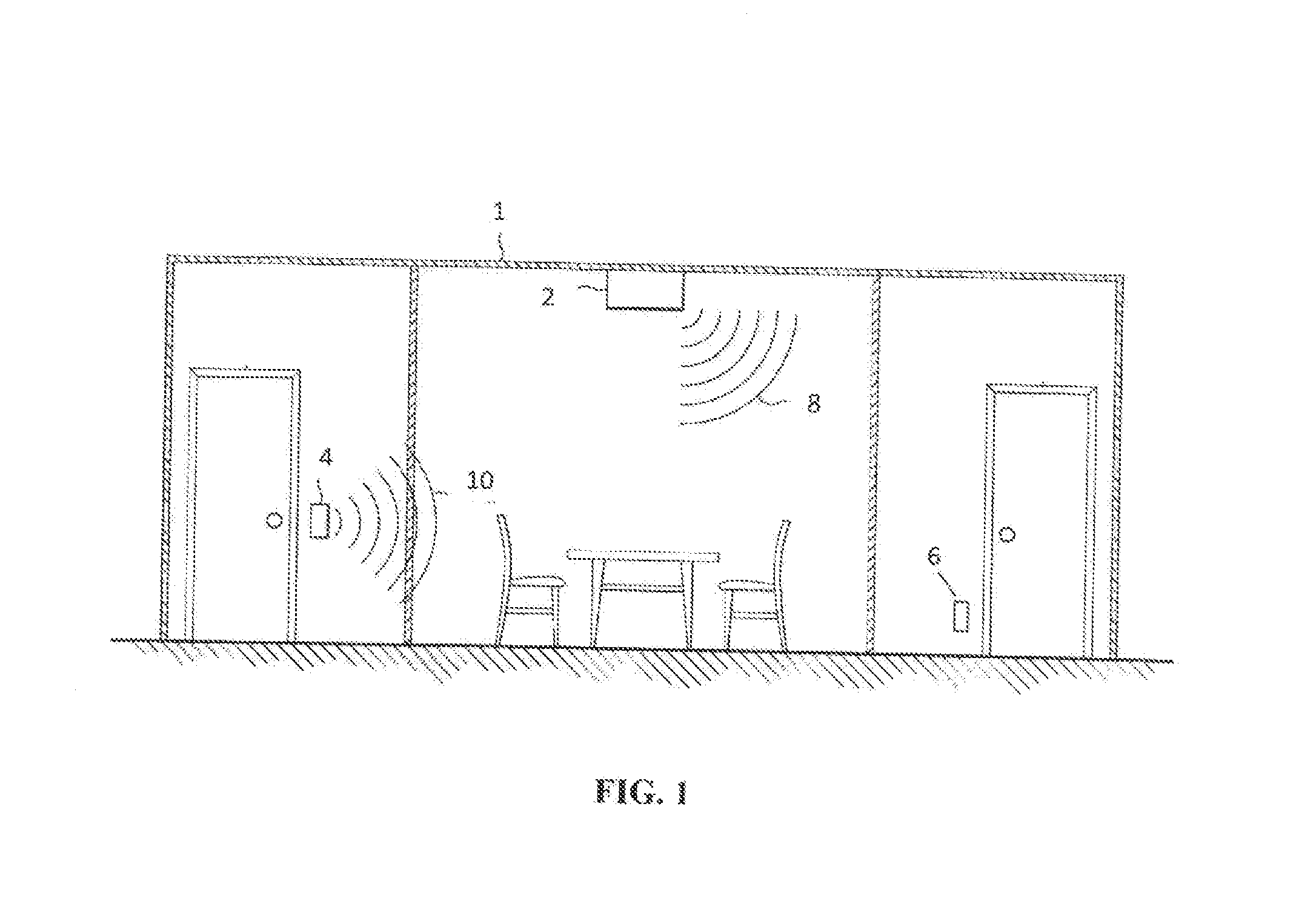
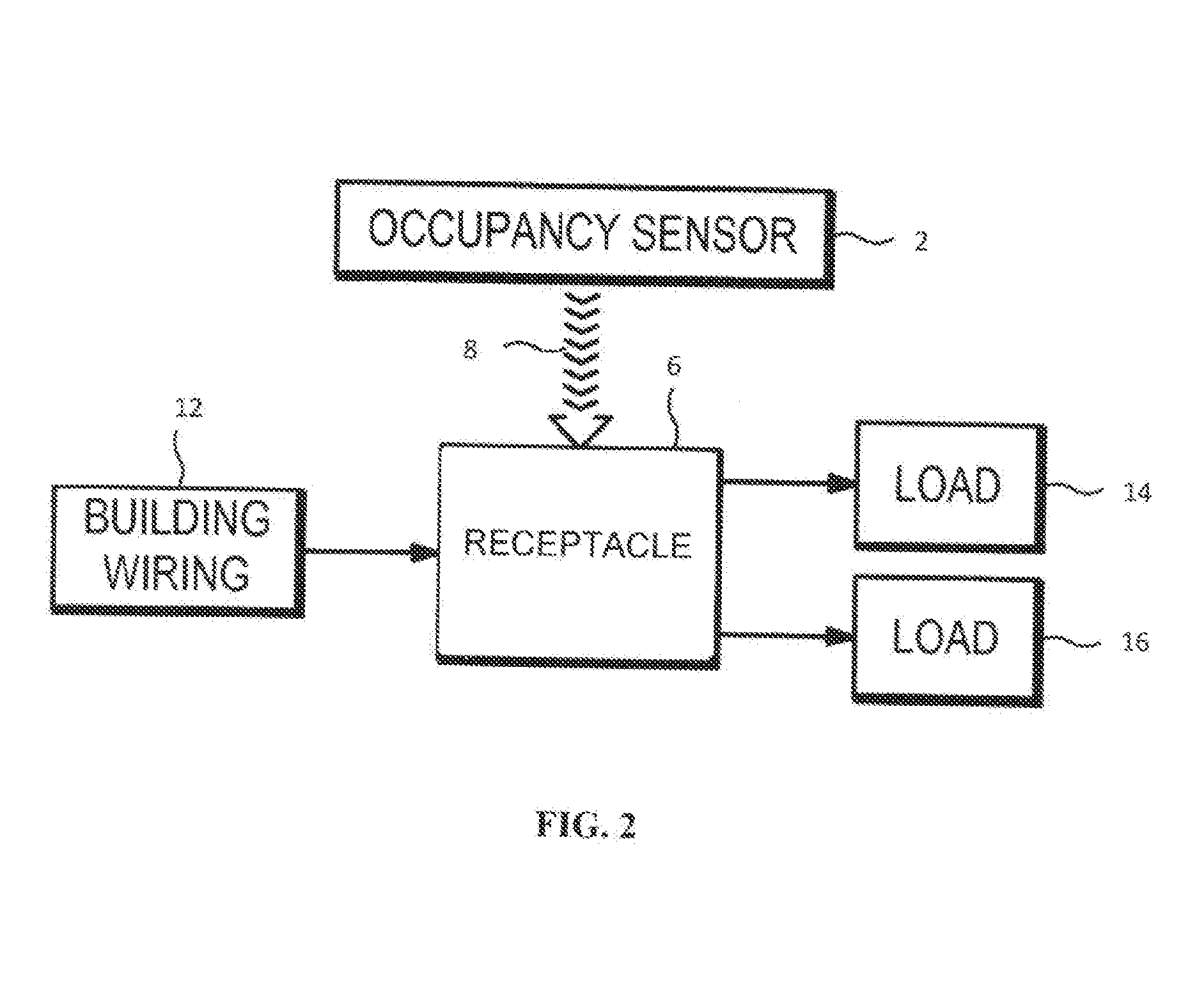
[0024]An electrical receptacle is disclosed for use in conjunction with one or more wireless occupancy sensors, unpowered switches, keycards, and other wireless devices now or hereafter known to selectively control one or more connected alternating current (AC) powered loads. The receptacle may be wireless, and may be configured to facilitate local or remote access for programming, monitoring, and controlling connected loads for a building in order to optimize the efficiency of controlled devices based on schedules, occupancy, demand response, and / or local input. Embodiments will be described below while referencing the accompanying figures. The accompanying figures are merely examples and are not intended to limit the scope of the present disclosure.

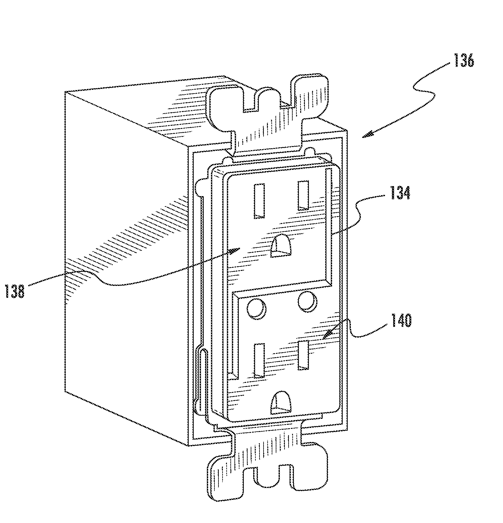
[0025]In one embodiment, the receptacle includes a wireless transceiver coupled to an antenna that is sandwiched between non-metallic layers of the receptacle. The antenna may be tuned for optimal performance and may be routed within th...


PUM


Abstract

A controllable electrical receptacle is disclosed. The electrical receptacle includes a housing having a pair of sockets suitable for receiving electrical plugs. The receptacle includes an antenna disposed beneath a cover portion of the receptacle. The antenna is configured to receive wireless signals from an occupancy sensor or other controller and to control power to the sockets based on the received signals. The antenna is also configured to transmit wireless signals. The antenna may be routed around the sockets to minimize interference caused by metal components of the receptacle. The antenna may be sandwiched between a pair of non-metal layers of the housing to avoid direct exposure to the environment while maintaining a desired performance. In one embodiment the antenna is a wire member received within a routing groove formed in a portion of the housing. The routing groove includes features for retaining the wire member in the groove.

Description

FIELD OF THE DISCLOSURE[0001]The disclosure generally relates to an electrical receptacle having an antenna, and more particularly to a wirelessly controlled electrical receptacle configured to receive and transmit wireless signals for controlling the electrical outlets of the electrical receptacle and for providing information relating to the operation of the receptacle.BACKGROUND OF THE DISCLOSURE[0002]Electrical receptacles provide a convenient means of supplying electrical power to electrical devices or appliances. In particular, indoor and outdoor lighting, appliances, and the like make use of an electrical distribution system through access of these electrical receptacles located in the interior and / or exterior walls of building structures such as homes and commercial buildings.[0003]Energy efficiency has become an increasingly important aspect of building design. To that end, many buildings now include programmable heating and cooling controls, and occupancy sensors are often...

Claims


Application Information

Patent Timeline
IPC IPC(8): H02J13/00
CPCH02J13/0075H01R13/7038H01R24/78H01R25/006H01R2103/00
Inventor PHAM, HOAWRIGHT, DANBETOURNAY, JASONMUTHU, SUBRAMANIAN
Owner LEVITON MFG
Why Eureka
Try Eureka