Alloy for r-t-b-based rare earth sintered magnet, process of producing alloy for r-t-b-based rare earth sintered magnet, alloy material for r-t-b-based rare earth sintered magnet, r-t-b-based rare earth sintered magnet, process of producing r-t-b-based rare earth sintered magnet, and motor

a rare earth, rtb-based technology, applied in the direction of magnets, magnetic circuits characterised by magnetic materials, magnets, etc., can solve the problem of not being able to obtain an r-t-b-based magnet having a sufficiently large coercive force, and achieve the effect of improving coercive force and improving coercive for

Inactive Publication Date: 2014-05-15
SHOWA DENKO KK
View PDF14 Cites 83 Cited by
  • Summary
  • Abstract
  • Description
  • Claims
  • Application Information

AI Technical Summary

Benefits of technology

[0019]As a result, it was found that, when an R-T-B-based magnet includes a main phase primarily containing R2Fe14B and a grain boundary containing more R than the main phase, and the grain boundary phase includes a grain boundary phase (R-rich phase) having a high concentration of rare earth elements which has been thus far known and a grain boundary phase (transition metal-rich phase) having a lower concentration of rare earth elements and a higher concentration of transition metal elements than a grain boundary

Problems solved by technology

However, in the related art, there were cases in which it was not possible to obtain an R-T-B-based magnet having a suffi

Method used


Image

  • Alloy for r-t-b-based rare earth sintered magnet, process of producing alloy for r-t-b-based rare earth sintered magnet, alloy material for r-t-b-based rare earth sintered magnet, r-t-b-based rare earth sintered magnet, process of producing r-t-b-based rare earth sintered magnet, and motor
  • Alloy for r-t-b-based rare earth sintered magnet, process of producing alloy for r-t-b-based rare earth sintered magnet, alloy material for r-t-b-based rare earth sintered magnet, r-t-b-based rare earth sintered magnet, process of producing r-t-b-based rare earth sintered magnet, and motor
  • Alloy for r-t-b-based rare earth sintered magnet, process of producing alloy for r-t-b-based rare earth sintered magnet, alloy material for r-t-b-based rare earth sintered magnet, r-t-b-based rare earth sintered magnet, process of producing r-t-b-based rare earth sintered magnet, and motor

Examples


first embodiment

[0079]“Alloy for R-T-B-Based Rare Earth Sintered Magnets”

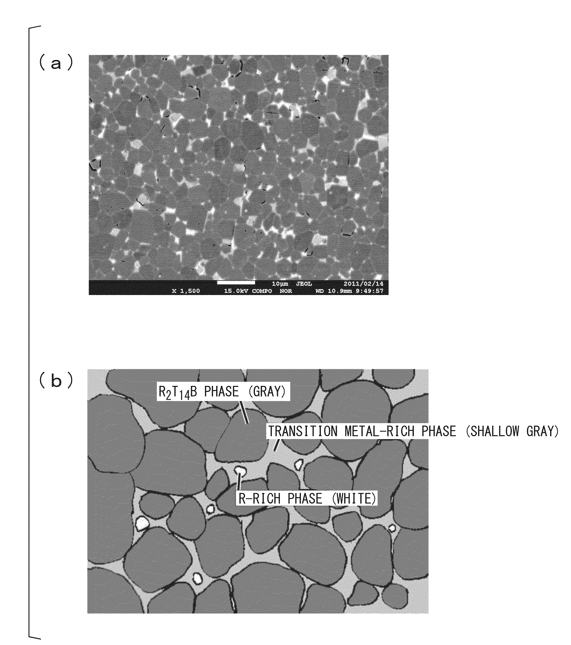
[0080]An alloy for R-T-B-based rare earth sintered magnets of the present embodiment (hereinafter abbreviated to “R-T-B-based alloy”) is an alloy used to produce an R-T-B-based rare earth sintered magnet (hereinafter abbreviated to “R-T-B-based magnet”) of the invention formed by molding and sintering a sintered body including a main phase primarily containing R2Fe14B and a grain boundary phase containing more R than the main phase, in which the grain boundary phase includes an R-rich phase and a transition metal-rich phase that is a grain boundary phase having a lower concentration of rare earth elements and a higher concentration of transition metal elements than the R-rich phase.

[0081]In the embodiment, the R-rich phase is a phase in which the concentration of all atoms of R which is rare earth elements is 70 at % or more. The transition metal-rich phase is a phase in which the concentration of all atoms of the rare earth e...

second embodiment

[0162]In the first embodiment, the R-T-B-based magnet was produced using the R-T-B-based alloy containing the metallic element; however, in a second embodiment, unlike the first embodiment, the R-T-B-based magnet will be produced using an alloy material for R-T-B-based rare earth sintered magnets containing a powder-form R-T-B-based alloy containing no metallic element and an additional metal (hereinafter, abbreviated to “R-T-B-based alloy material”).

[0163]When the R-T-B-based alloy material of the present embodiment is molded and sintered in the same manner as in the first embodiment, the R-T-B-based magnet of the first embodiment can be obtained.

[0164]The R-T-B-based alloy material of the embodiment is an R-T-B-based alloy material including an R-T-B-based alloy containing R which is a rare earth element, T which is a transition metal essentially containing Fe, B and inevitable impurities, in which R accounts for 13 at % to 15 at %, B accounts for 4.5 at % to 6.2 at %, T accounts ...

third embodiment

[0186]In the second embodiment, the R-T-B-based alloy material containing the powder-form R-T-B-based alloy containing no metallic element and the additional metal has been described, however, in the present embodiment, an R-T-B-based alloy material containing an R-T-B-based alloy containing a metallic element and the additional metal will be described. That is, in the invention, the metallic element may be added to the R-T-B-based alloy material in a step of casting the R-T-B-based alloy, in a step before the sintering of the R-T-B-based alloy, or in both steps.

[0187]In a third embodiment, some of the metallic element contained in the R-T-B-based alloy material is added to the R-T-B-based alloy, and the powder of the R-T-B-based alloy and the remnant of the metallic element are mixed, thereby preparing an R-T-B-based alloy material, and an R-T-B-based magnet is produced using the R-T-B-based alloy material.

[0188]When the R-T-B-based alloy material of the embodiment is molded and si...


PUM

PropertyMeasurementUnit
Temperatureaaaaaaaaaa

Abstract

An alloy for R-T-B-based rare earth sintered magnets which contains R which is a rare earth element; T which is a transition metal essentially containing Fe; a metallic element M containing one or more metals selected from Al, Ga and Cu; B and inevitable impurities, in which R accounts for 13 at % to 15 at %, B accounts for 4.5 at % to 6.2 at %, M accounts for 0.1 at % to 2.4 at %, T accounts for balance, a proportion of Dy in all rare earth elements is in a range of 0 at % to 65 at %, and the following Formula 1 is satisfied,
0.0049Dy+0.34≦B/TRE≦0.0049Dy+0.36  Formula 1
wherein Dy represents a concentration (at %) of a Dy element, B represents a concentration (at %) of a boron element, and TRE represents a concentration (at %) of all the rare earth elements.

Description

[0001]The present invention relates to an alloy for R-T-B-based rare earth sintered magnets, a process of producing the alloy for R-T-B-based rare earth sintered magnets, an alloy material for R-T-B-based rare earth sintered magnets, an R-T-B-based rare earth sintered magnet, a process of producing the R-T-B-based rare earth sintered magnet, and a motor, and particularly to an alloy for R-T-B-based rare earth sintered magnets and an alloy material for R-T-B-based rare earth sintered magnets which have excellent magnetic properties and from which R-T-B-based rare earth sintered magnets that are preferably used for motors can be obtained.[0002]Priority is claimed on Japanese Patent Application No. 2011-151815 filed Jul. 8, 2011, Japanese Patent Application No. 2011-229289 filed Oct. 18, 2011, Japanese Patent Application No. 2012-060259 filed Mar. 16, 2012, and Japanese Patent Application No. 2012-149560 filed Jul. 3, 2012, the contents of which are incorporated herein by reference.BAC...

Claims


Application Information

Patent Timeline
IPC IPC(8): H01F1/01
CPCH01F1/01B22F3/24C21D6/00C22C33/0278C22C38/002C22C38/005C22C38/02C22C38/06C22C38/10C22C38/16H01F1/0577H01F1/058H01F41/0293B22F3/16B22F2003/248H01F1/0536H02K1/02
Inventor NAKAJIMA, KENICHIROYAMAZAKI, TAKASHI
Owner SHOWA DENKO KK
Why Eureka
Try Eureka