Color matched coating for bus bars

a technology of color matching and bus bars, applied in the direction of door/window protective devices, instruments, printing, etc., can solve the problems of affecting affecting the performance and a partial leakage of the inert gas stored in the dead air, so as to improve the aesthetics of the ec device and ensure robust durable performance. , the effect of increasing the aesthetic appearan

Inactive Publication Date: 2014-05-15
SAGE ELECTROCHROMICS
View PDF12 Cites 42 Cited by
  • Summary
  • Abstract
  • Description
  • Claims
  • Application Information

AI Technical Summary

Benefits of technology

[0010]In some embodiments, the substantially non-porous, color-matched over-coating material is an ink. In some embodiments, the system further comprises a spacer, wherein the ink provides electrical insulation between the spacer and the at least one bus bar. In some embodiments, the ink masks the porosity of the at least one bus bar and increases inert gas retention performance. In some embodiments, the system further comprises a solder pad, wherein the ink acts as a solder stop by not covering said solder pad.
[0015]In some embodiments, the non-porous color-matched over-coating material is an ink. In some embodiments, the system further comprises a spacer, wherein the ink provides electrical insulation between the spacer and the bus bars. In some embodiments, the ink masks the porosity of the bus bars and increases inert gas retention performance. In some embodiments, the system further comprises a solder pad, wherein the ink acts as a solder stop by not covering the solder pad.
[0019]In a further aspect, the present invention comprises a method of increasing the inert gas retention performance of an electrochromic device including at least one bus bar and a color obscuration material comprising at least partially coating the at least one bus bar with an over-coating material that is 1) substantially non-porous; and 2) substantially color-matched to one of said color obscuration material, a spacer, or a polymer seal.
[0023]This invention is believed to increase the aesthetic appearance of EC IGU and guarantees robust durable performance in the field over the lifetime of the IGU.

Problems solved by technology

An internal connection to the transparent conductor layer would, it is believed, compromise the aesthetics of the EC device.
As a result, there is believed to be at least a partial leakage of the inert gas stored in the dead air space of the IGU when traditional frit materials are extended outside the IGU under the spacer.
In addition, traditional electrochromic IGU constructions have certain deficiencies with regards to the visual aspect of the bus bars.
The color difference may be striking and may attract some attention.

Method used


Image

  • Color matched coating for bus bars
  • Color matched coating for bus bars
  • Color matched coating for bus bars

Examples


Embodiment Construction

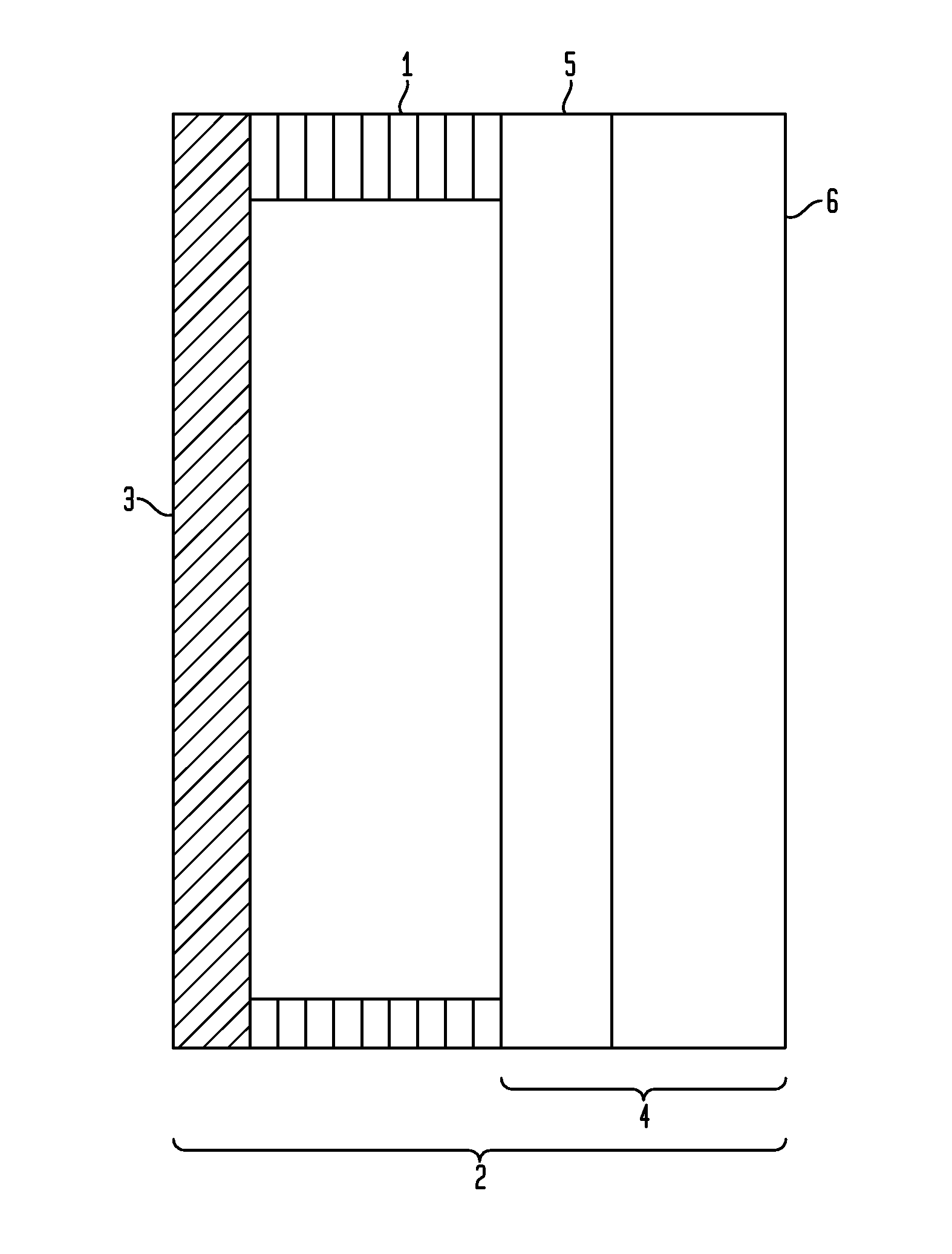
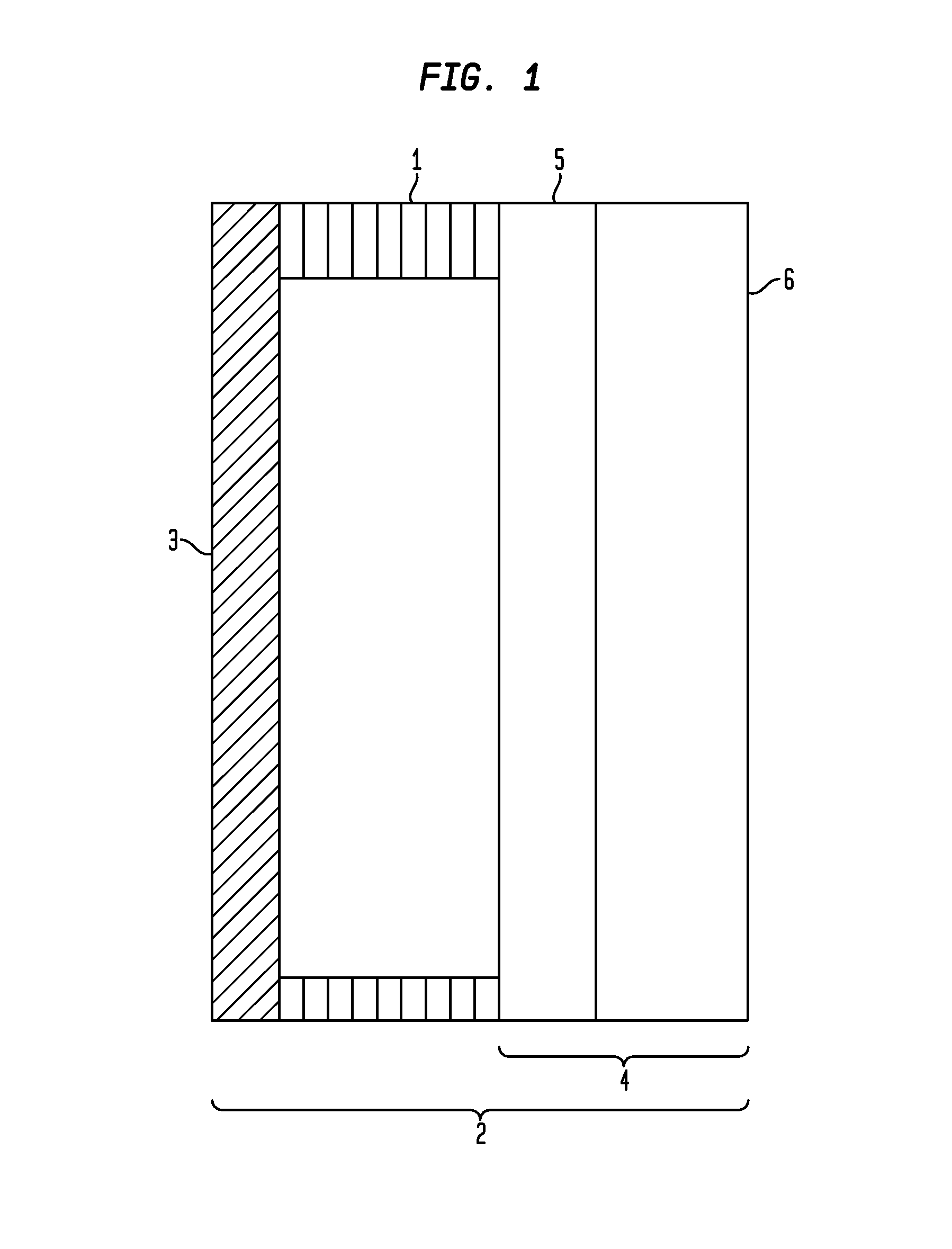
[0029]A thin film electrochromic (EC) device used in architectural window applications changes tint from clear to dark upon the application of low-voltage DC power. The EC device is deposited on a glass substrate which is incorporated into an insulating glass unit (IGU). This invention provides enhancements to the electrochromic IGU.

[0030]FIGS. 4 and 5 illustrate the electrochromic IGU construction, bus bars, and specific features of the proposed invention. The electrochromic dual pane IGU consists of two glass substrates (lites) separated by an adhesively bonded spacer which completely traverses their perimeter and encloses the desiccated and inert gas filled space between the substrates. In some embodiments, the spacer and the adhesive polymer seal are black (but could be any other aesthetically attractive or functional color, shade or hue of black or grey). The electrochromic thin film coatings are deposited on one of the substrates. The substrate may be a laminate consisting of ...


PUM

PropertyMeasurementUnit
distanceaaaaaaaaaa
distanceaaaaaaaaaa
optical densityaaaaaaaaaa

Abstract

In one aspect, the present invention is a system comprising an electrochromic device having at least one bus bar and a color obscuration material wherein the at least one bus bar is coated with an over-coating material that is 1) substantially non-porous; and 2) substantially color-matched to one of said color obscuration material, a spacer, or a polymer seal.

Description

CROSS-REFERENCE TO RELATED APPLICATIONS[0001]The present application claims the benefit of the filing date of U.S. Provisional Patent Application No. 61 / 726,146 filed Nov. 14, 2012, the disclosure of which is hereby incorporated herein by referenceFIELD OF THE INVENTION[0002]The present application relates to quality and performance enhancements related to electrochromic insulating glass units.BACKGROUND OF THE INVENTION[0003]Electrochromic glazings include electrochromic materials that are known to change their optical properties, such as coloration, in response to the application of an electrical potential, thereby making the device more or less transparent or more or less reflective. Typical prior art electrochromic devices (hereinafter “EC devices”) include a counter electrode layer, an electrochromic material layer which is deposited substantially parallel to the counter electrode layer, and an ionically conductive layer separating the counter electrode layer from the electroch...

Claims


Application Information

Patent Timeline
Patent Type & Authority Applications(United States)
IPC IPC(8): G02F1/153
CPCG02F1/153B32B17/10513G02F1/161G02F2001/1536B32B17/10055E06B9/24E06B2009/2464G02F1/163G02F2202/00G02F1/1533G02F2001/1555G02F1/155
Inventor SBAR, NEIL L.SAVARY, JEAN-PHILIPPE
Owner SAGE ELECTROCHROMICS
Why Eureka
Try Eureka