Rack and power control method thereof

a power control method and power control technology, applied in the direction of power supply for data processing, instruments, liquid/fluent solid measurement, etc., can solve the problems of excessive power consumption and excessive power consumption

Active Publication Date: 2014-05-15
INVENTEC PUDONG TECH CORPOARTION +1
View PDF2 Cites 3 Cited by
  • Summary
  • Abstract
  • Description
  • Claims
  • Application Information

AI Technical Summary

Benefits of technology

[0007]An embodiment of the disclosure provides a power control method of a rack. The rack has a plurality of nodes. The power control method of the rack comprises the following steps. Power information of each of the plurality of nodes is received. A total power consumption value of the plurality of nodes according to the power information is calculated. A number of power supply units to be turned on according to the total power consumption value and a maximum supplied power value of a single power supply unit is calculated. At least one primary power supply unit and at least one secondary power supply unit in pairs according to the number of power supply units to be turned on are started, so that the at least one primary power supply unit provides a duty voltage to the plurality of nodes, and the at least one secondary power supply unit does not provide the duty voltage to the plurality of nodes. An input source of at least one primary power supply unit and an input source of the at least one secondary power supply unit are different.
[0008]Another embodiment of the disclosure provides a rack comprising a plurality of primary power supply units, a plurality of secondary power supply units, a plurality of nodes, a rack management controller (RMC), and a control unit. The plurality of primary power supply units are configured to respectively provide a duty voltage. The plurality of secondary power supply units are configured to respectively provide the duty voltage. The primary power supply units and the secondary power supply units receive different input sources. The plurality of nodes are configured to respectively provide power information. The RMC, coupled to the plurality of nodes, is configured to receive the power information, to calculate a total power consumption value of the plurality of nodes according to the power information, and to calculate a number of power supply units to be turned on according to the total power consumption value and a maximum supplied power value of a single power supply unit. The control unit, coupled to the RMC, the primary power supply units, and the secondary power supply units, is configured to receive the number of power supply units to be turned on and generate a plurality of control signals according to the number of power supply units to be turned on, so as to start at least one of the primary power supply units and at least one of the secondary power supply units in pairs. Therefore, the at least one of the primary power supply units provides the duty voltage to the plurality of nodes, and the at least one of the secondary power supply units does not supply the duty voltage to the plurality of nodes.
[0009]Yet another embodiment of the disclosure comprises a rack, comprising a rack management controller (RMC) and a control unit. The rack management controller is coupled to a plurality of nodes and is configured to receive power information therefrom, to calculate a total power consumption value of the plurality of nodes according to the power information, and to calculate a number of power supply units to be turned on according to the total power consumption value and a maximum supplied power value of a single power supply unit. The control unit is coupled to the RMC, the primary power supply units and the secondary power supply units. The control unit is configured to receive the number of power supply units to be turned on and to generate a plurality of control signals according to the number of power supply units to be turned on.

Problems solved by technology

However, under this concept, the server nodes are limited to division of work, and cannot cooperate with each other, which often results in the scenario that all the server nodes in a data center simultaneously operate in almost the same performance state, resulting in excessive power consumption.
However, during actual operation of the server, since the server nodes are not always in a full-load state, excessive power consumption is caused.

Method used


Image

  • Rack and power control method thereof
  • Rack and power control method thereof
  • Rack and power control method thereof

Examples


Embodiment Construction

[0014]In the following detailed description, for purposes of explanation, numerous specific details are set forth in order to provide a thorough understanding of the disclosed embodiments. It will be apparent, however, that one or more embodiments may be practiced without these specific details. In other instances, well-known structures and devices are schematically shown in order to simplify the drawings.

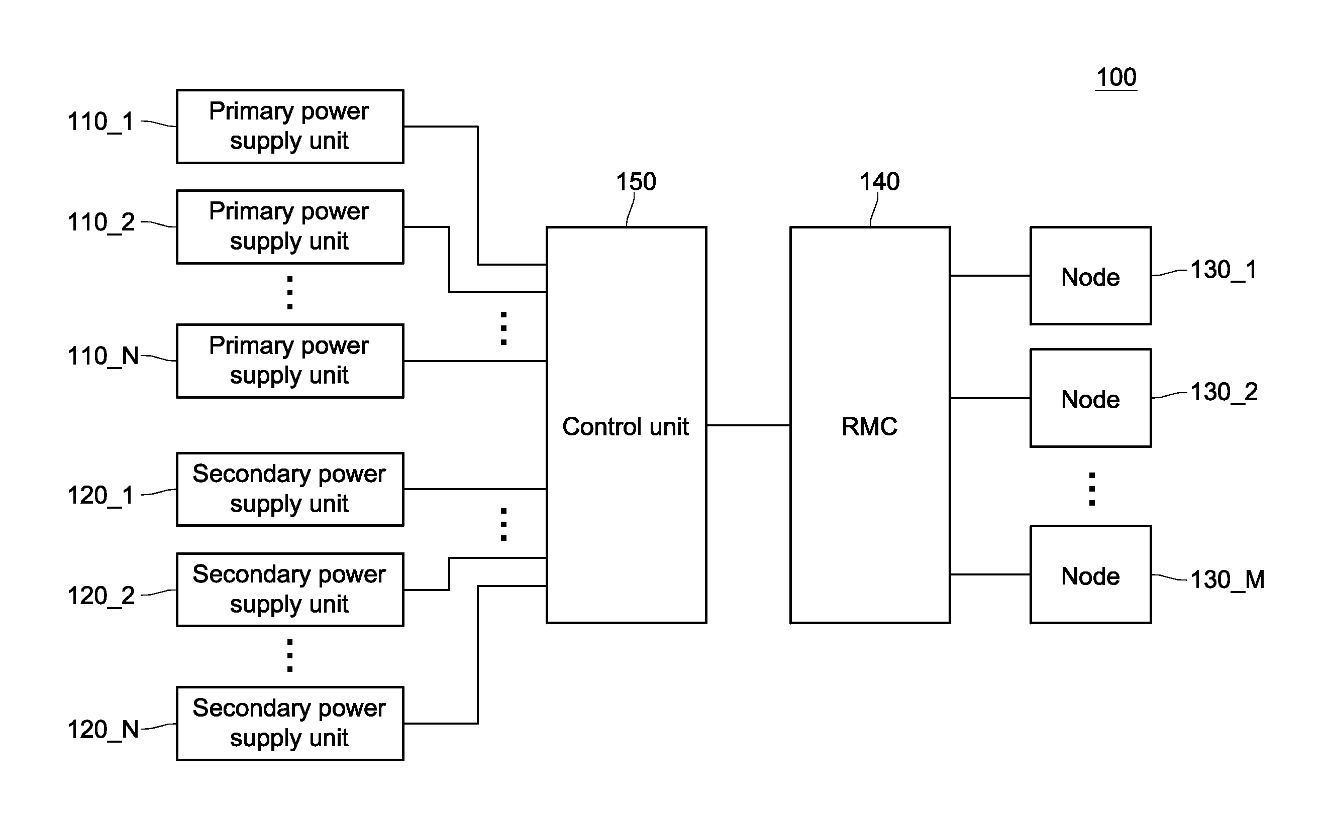
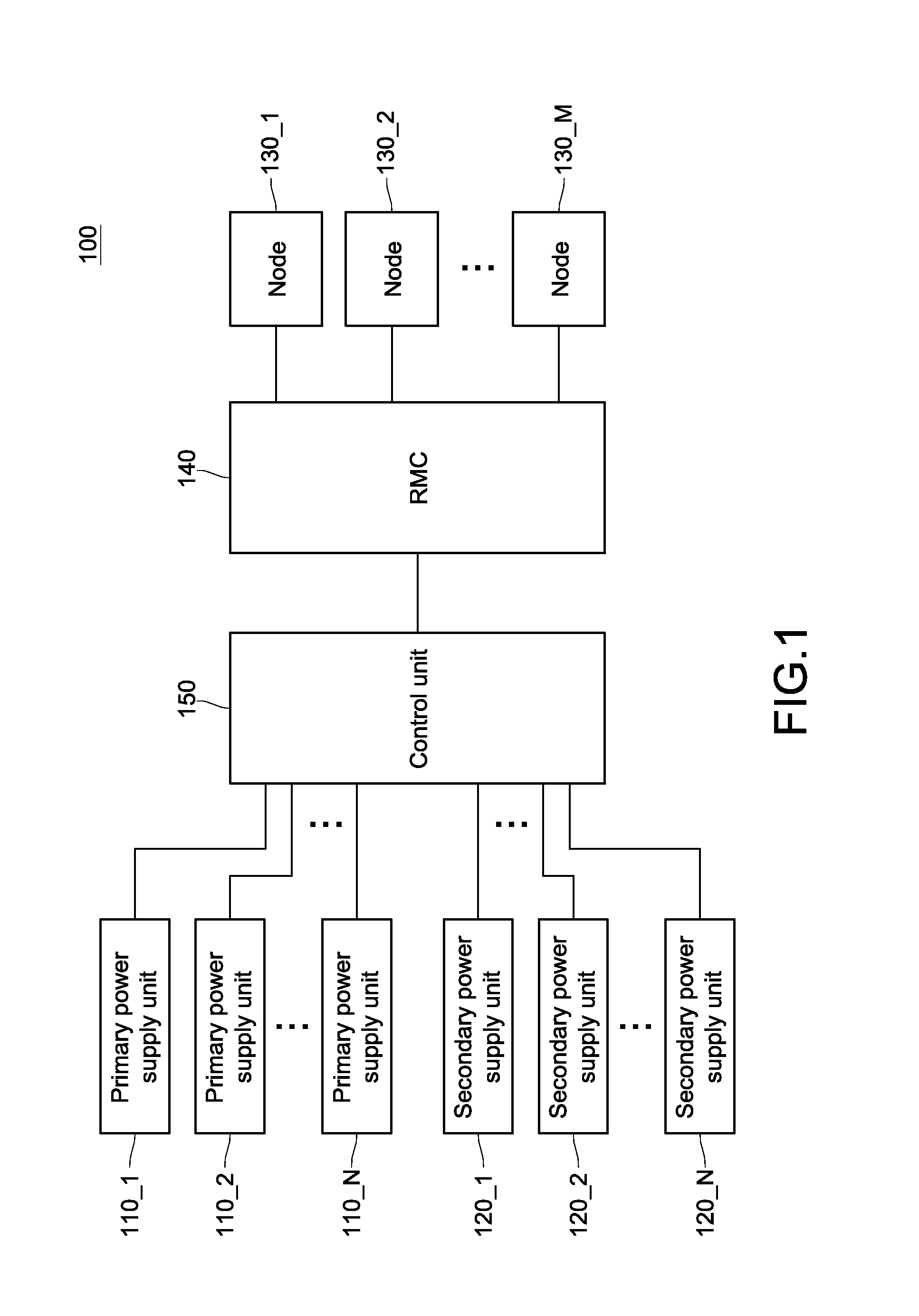
[0015]FIG. 1 is a schematic view of a rack according to an embodiment of the disclosure. The rack 100 comprises a plurality of primary power supply units 110_1˜110_N, a plurality of secondary power supply units 120_1˜120_N, a plurality of nodes 130_1˜130_M, an RMC 140, and a control unit 150. In this disclosure, N and M are positive integers greater than 1, and N and M may be the same or different.

[0016]The primary power supply units 110_1˜110_N are configured to respectively provide a duty voltage. That is to say, when the primary power supply units 110_1˜110_N are in a normal sta...


PUM


Abstract

A power control method of a rack having a plurality of nodes includes the following steps. Power information of each node is received. a total power consumption value of the plurality of nodes according to the power information is calculated. A number of power supply units to be turned on according to the total power consumption value and a maximum supplied power value of a single power supply unit is calculated. At least one primary power supply unit and at least one secondary power supply unit in pairs according to the number of power supply units to be turned on is started. The at least one primary power supply unit provides a duty voltage to the plurality of nodes, and the at least one secondary power supply unit does not provide the duty voltage to the plurality of nodes.

Description

CROSS-REFERENCE TO RELATED APPLICATIONS [0001]This non-provisional application claims priority under 35 U.S.C. §119(a) on Patent Application No(s). 201210460312.1 filed in China on Nov. 15, 2012, the entire contents of which are hereby incorporated by reference.BACKGROUND OF THE INVENTION [0002]1. Field of the Invention[0003]The disclosure relates to a power control method, and more particularly to a rack and a power control method thereof.[0004]2. Description of the Related Art[0005]Generally speaking, performance and efficacy of individual servers are emphasized nowadays. Based on this concept, servers are designed in consideration of division of work and independent operation. That is to say, each server node dynamically adjusts its energy consumption according to its state and in consideration of tradeoffs between energy saving and performance.[0006]However, under this concept, the server nodes are limited to division of work, and cannot cooperate with each other, which often re...

Claims


Application Information

Patent Timeline
Patent Type & Authority Applications(United States)
IPC IPC(8): G06F1/32
CPCG06F1/3296Y02D10/00G06F1/3206G06F1/20G06F1/26G06F1/32G06F1/263G06F1/30G06F1/3203G06F11/2015
Inventor KUAN, HAO-YENWANG, SHU-YEN
Owner INVENTEC PUDONG TECH CORPOARTION
Why Eureka
Try Eureka