AI technical title is built by Patsnap AI team. It summarizes the technical point description of the patent document.
a washing machine and washing machine technology, applied in the field of washing machines, can solve the problems of excessive consumption of washing water, wet laundry, etc., and achieve the effects of improving washing and rinsing performance, improving spray speed, and ensuring spray rang
Inactive Publication Date: 2014-05-22
LG ELECTRONICS INC
View PDF4 Cites 2 Cited by
Summary
Abstract
Description
Claims
Application Information
AI Technical Summary
This helps you quickly interpret patents by identifying the three key elements:
Problems solved by technology
Method used
Benefits of technology
Benefits of technology
The present invention is a washing machine that can spray water to both the side wall and bottom of the washing tub, which improves the wetness and washing performance of the laundry. The spray nozzle has a flat face without a bend, allowing for straight spraying, which improves spray speed and range. When the washing tub is at its minimum load, the spray nozzle sprays water to the side wall and bottom, while at its maximum load, the spray nozzle prevents water from flowing out of the washing tub. This ensures both side wall and bottom spraying, regardless of the load on the washing tub. The spray nozzle also includes a flat spray range that allows for effective wetness of the laundry. This washing machine demonstrates improved performance and efficiency in wetting laundry and rinsing clothes.
Problems solved by technology
However, the related art washing machine performs washing such that washing water is supplied toward the bottom of a washing tub and, as the supplied washing water fills the washing tub, the laundry is wet.
Thus, in order to wet all the laundry, water must be supplied as high the laundry, causing a problem in that an excessive amount of washing water is consumed.
At this time, the laundry cling to the side wall of the washing tube due to the high speed rotation of the washing tub, and in order to rinse the clinging laundry, washing water must be supplied as high as the position whether the laundry cling, resulting in consumption of an excessive amount of washing water.
In particular, because the process is intermittently repeated during the washing process, further increasing the amount of consumed washing water.
Method used
Image
Click on the blue label to locate the original text in one second.
Reading with bidirectional positioning of images and text.
Examples
Embodiment Construction
[0039]The foregoing and other objects, features, aspects and advantages of the present invention will become more apparent from the following detailed description of the present invention when taken in conjunction with the accompanying drawings. Exemplary embodiments of the present invention will now be described in detail with reference to the accompanying drawings. The invention may, however, be embodied in many different forms and should not be construed as being limited to the embodiments set forth herein. Rather, these embodiments are provided so that this disclosure will be thorough and complete, and will fully convey the scope of the invention to those skilled in the art. In the drawings, the shapes and dimensions may be exaggerated for clarity, and the same reference numerals will be used throughout to designate the same or like components.
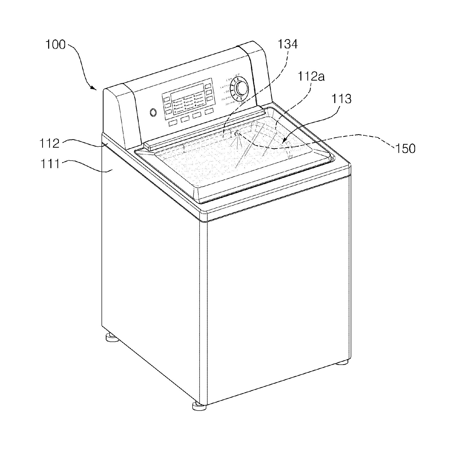
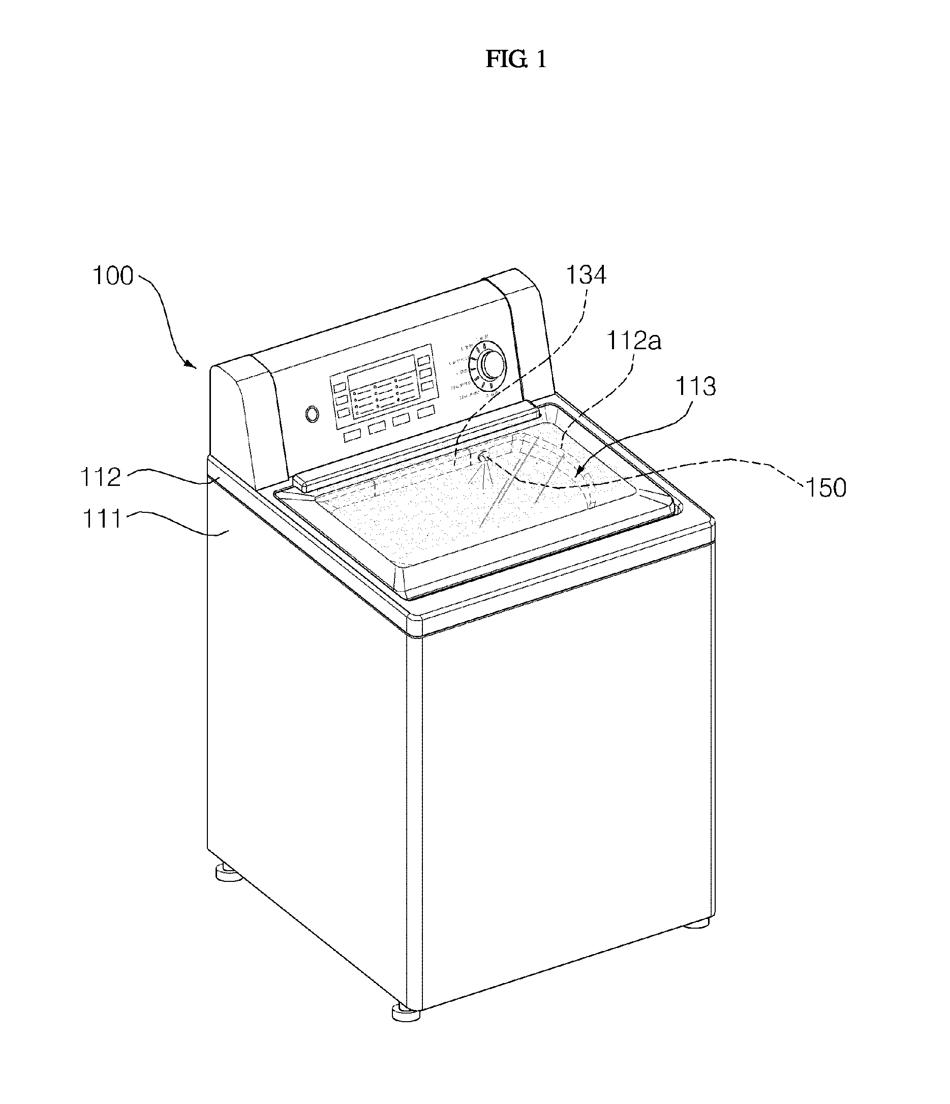
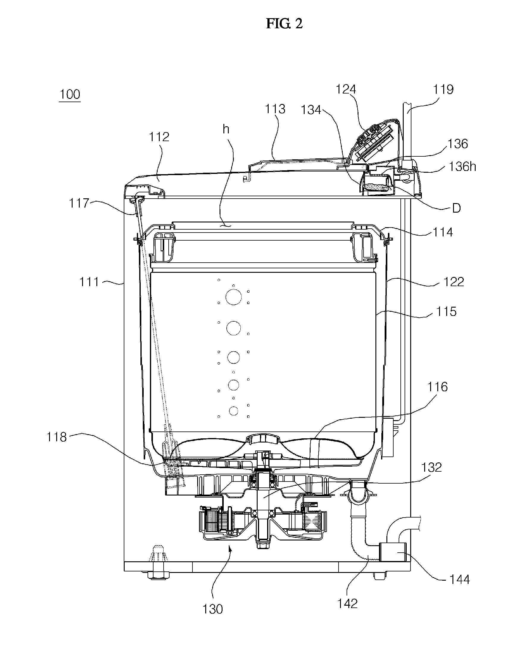
[0040]FIG. 1 is a perspective view of a washing machine according to an exemplary embodiment of the present invention. FIG. 2 is a side s...
PUM
Abstract
A washing machine includes: a cabinet forming an external appearance and having an open upper portion; a reservoir hanging within the cabinet and allowing washing water to be put therein; a washing tub rotatably disposed within the reservoir and accommodating the laundry; and a spray nozzle spraying washing water into the washing tub such that one boundary of sprayed washing machine reaches a side wall of the washing tub and the other boundary of the sprayed washing water reaches the bottom of the washing tub, wherein the spray nozzle includes: a tube part forming a passage along which washing water is introduced; and a spray part connected with the tube part to spray washing water and disposed such that a spray face against which washing water discharged from the tube part splashes is bent at a certain angle with respect to a discharge direction of the tube part. The laundry can be effectively wet by increasing a spray range of washing water.
Description
[0001]This application is a continuation of U.S. patent application Ser. No. 12 / 753,584, filed Apr. 2, 2010, which claims priority from Korean Patent Application Nos. 10-2009-0029134, filed on Apr. 3, 2009, 10-2009-0029139, filed on Apr. 3, 2009, 10-2009-0099905, filed on Oct. 20, 2009, 10-2009-0109908, filed on Nov. 13, 2009, and 10-2010-0006144, filed on Jan. 22, 2010, the disclosures of which are incorporated herein by reference in their entireties.BACKGROUND OF THE INVENTION[0002]1. Field of the Invention[0003]The present invention relates to a washing machine and, more particularly, to a washing machine capable of simultaneously spraying washing water to a side wall and bottom of a washing tub to effectively rinse the laundry.[0004]2. Description of the Related Art[0005]A washing machine generally refers to various devices for processing the laundry by applying a physical and chemical action to the laundry, such as a laundry machine for detaching a contaminant from the clothes,...
Claims
Application Information
Patent Timeline
Application Date:The date an application was filed.
Publication Date:The date a patent or application was officially published.
First Publication Date:The earliest publication date of a patent with the same application number.
Issue Date:Publication date of the patent grant document.
PCT Entry Date:The Entry date of PCT National Phase.
Estimated Expiry Date:The statutory expiry date of a patent right according to the Patent Law, and it is the longest term of protection that the patent right can achieve without the termination of the patent right due to other reasons(Term extension factor has been taken into account ).
Invalid Date:Actual expiry date is based on effective date or publication date of legal transaction data of invalid patent.
Patent Type & AuthorityApplications(United States)
IPC IPC(8): D06F35/00
CPCD06F17/04
InventorLEE, KYU BUMKIM, YOUNG JONGLEE, SANG JUNPARK, YOUNG BAE

