Double-Walled Dry Heat Exchanger Coil With Single-Walled Return Bends

a heat exchanger coil and return bend technology, applied in the field of non-vaporative or “ dry” heat exchangers, can solve the problem that ships can be left stranded without power

Active Publication Date: 2014-05-22
EVAPCO
View PDF13 Cites 10 Cited by
  • Summary
  • Abstract
  • Description
  • Claims
  • Application Information

AI Technical Summary

Benefits of technology

[0007]According to an embodiment of the invention, capturing leaks outside of the airstream allows a dry transformer to continue operating, notwithstanding the existence of a leak. In the case of a marine transformer on a ship, this embodiment allows a ship to continue operating long enough to return to port for repair.
[0009]According to an embodiment of the invention, connecting the inner tubes using return bends, thereby avoiding chambered headers, allows for more flexibility in coil circuit design.
[0015]According to an embodiment of the invention, the coils may be situated in the bottom portion of a housing or “box” which is attached to a transformer transfer box. Fans located in the top portion of the housing draw air from the transfer box and force it down over the coils where it is cooled, and the cooled air then exits the housing and returns to the transfer box. Heat transfer is facilitated with the use of fins fixed to the outside surfaces of the outer / safety tubes.
[0017]While the present invention is described in the context of a heat exchanger in which water is used to cool air that in turn is used to cool a power transformer, the invention is equally suited to other types of heat exchange. For example, persons of ordinary skill in the art would readily recognize that the invention can be equally used to effect heat exchange in reverse, whereby air passing over the coils can be used to receive heat from a process / industrial fluid contained in the coil, thereby cooling the process fluid.

Problems solved by technology

A “dry” cooling solution is required for marine transformers because if water contact causes a ship or other marine transformer to short circuit and fail, the ship can be left stranded without power.

Method used


Image

  • Double-Walled Dry Heat Exchanger Coil With Single-Walled Return Bends
  • Double-Walled Dry Heat Exchanger Coil With Single-Walled Return Bends
  • Double-Walled Dry Heat Exchanger Coil With Single-Walled Return Bends

Examples


Embodiment Construction

[0026]In the following description, numerous details are set forth to provide a more thorough explanation of the present invention. It will be apparent, however, to one skilled in the art, that the present invention may be practiced without these specific details.

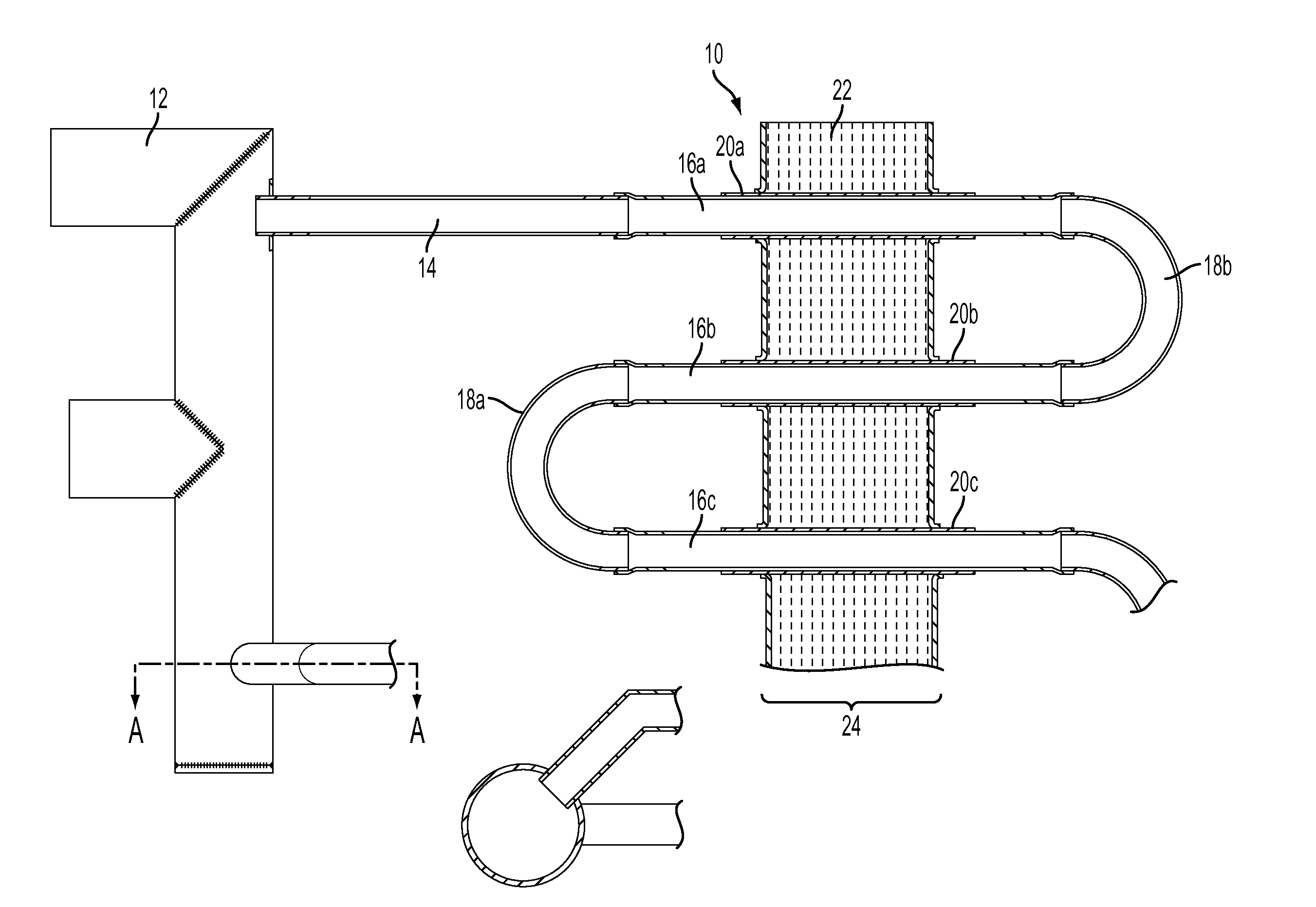
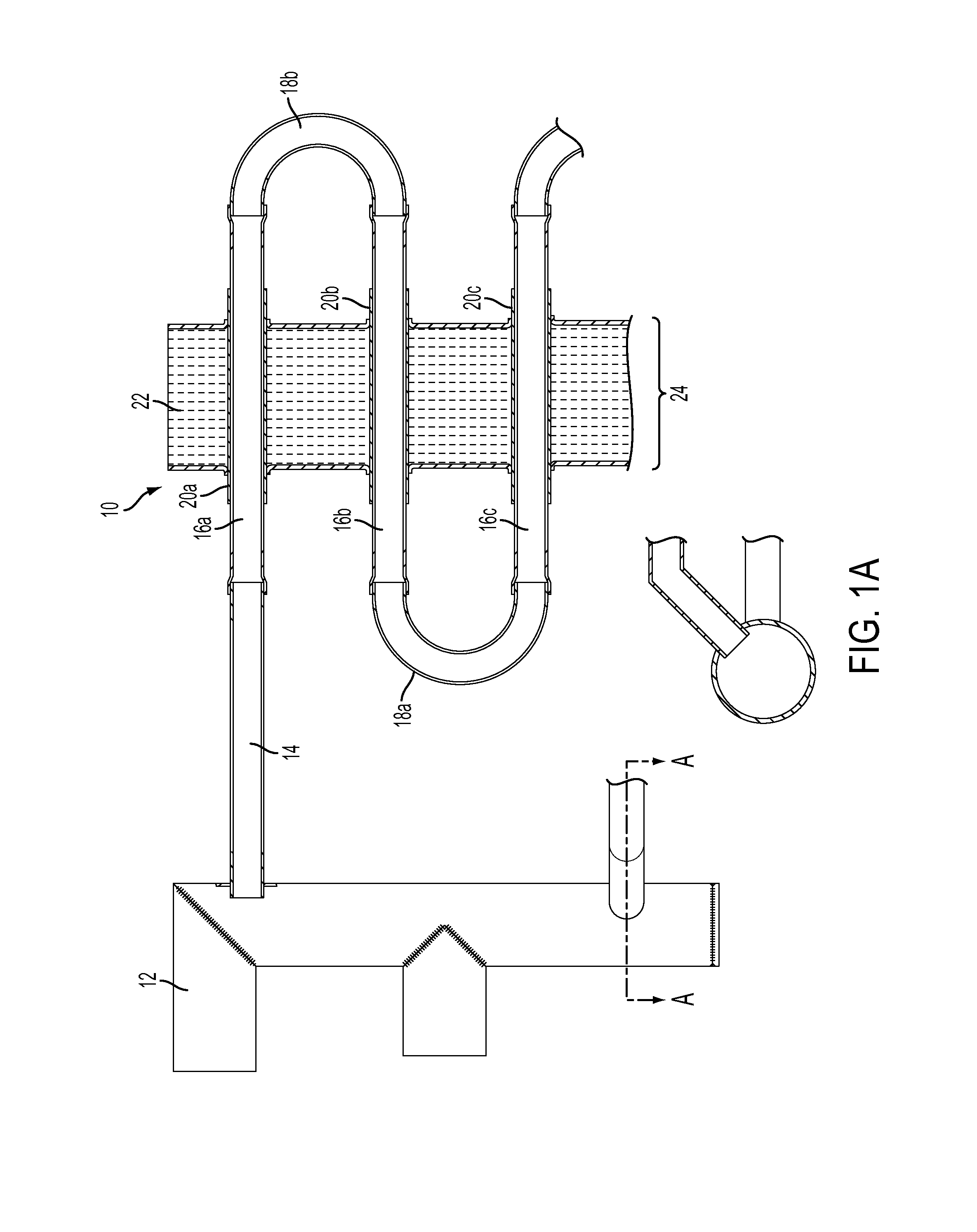
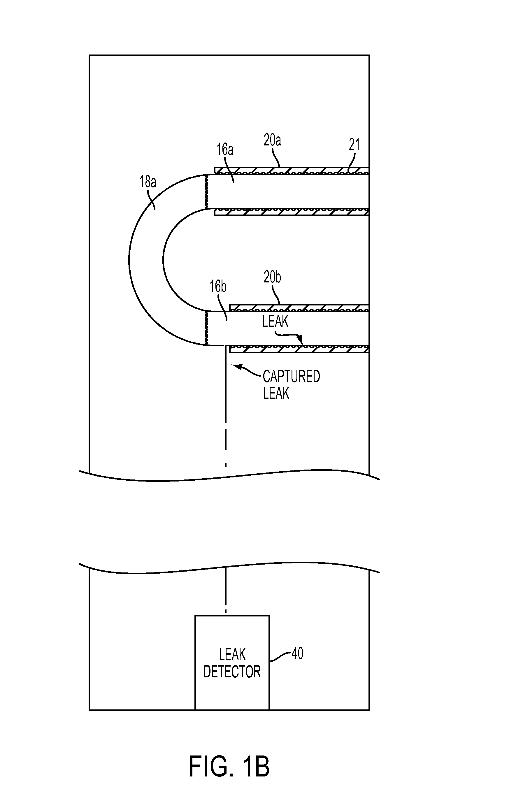
[0027]FIG. 1A shows a heat exchange coil 10 according to an embodiment of the invention. Heat exchange coil 10 receives fluid from header 12 through connecting tube 14. Connecting tube 14 is connected to inner tube 16a. Fluid travels through the heat exchange coil through inner tubes 16a, 16b, and 16c, via return bends 18a and 18b Inner tubes 16a, 16b, and 16c are expanded into outer tubes 20a, 20b, and 20c, respectively. According to an embodiment of the invention, the inner surfaces of outer tubes 20a, 20b, and 20c have dimples, ribs, or other surface features 21 to create both contact between and voids between the inner and outer tubes to allow the passage of fluid between them (see FIG. 1B). According to an alternative ...


PUM


Abstract

A dry heat exchanger coil having a plurality of straight inner tubes connected by a plurality of return bends. The return bends are located outside of the air flow passing over the coil. The inner tubes are situated within a corresponding outer or “safety” tube. The outer tubes do not contain and are not connected to return bends, but the ends of the outer tubes are located outside of the air flow path. Leaks in the inner tubes are captured by the outer tubes and the leaking fluid will flow in the space between the inner and outer tubes, flow out the end of the outer tube, to be captured in a drip pan at the bottom of the coil housing. Leaks occurring in the return bends will also be captured in drip pan.

Description

[0001]This application claims priority from U.S. Provisional Application No. 61 / 638,275, the disclosure of which is incorporated herein in its entirety.FIELD OF THE INVENTION[0002]The present invention relates to non-evaporative or “dry” heat exchangers, particularly those used to cool marine power transformers, although the invention can be used in any environment or situation where “dry” cooling solutions are required or desired.BACKGROUND OF THE INVENTION[0003]According to the prior art, the air used for cooling a transformer is passed over a series of coils through which water is circulated. The prior art dry transformer cooling coils consist of a series of straight double-walled tubes which terminate at each end in sealed chambered headers. The inner tubes of the straight tubes terminate in one chamber of the header, and the outer tubes terminate in a separate sealed chamber of the header. Cooling fluid is circulated through the inner tubes, and through the corresponding chambe...

Claims


Application Information

Patent Timeline
Patent Type & Authority Applications(United States)
IPC IPC(8): F28F17/00
CPCF28F17/005F28D7/085F28D7/1623F28D15/00F28F1/003
Inventor BYRNE, TOM
Owner EVAPCO
Why Eureka
Try Eureka