Balanced capillary bridge viscometer

a bridge and capillary technology, applied in the field of capillary viscometers, can solve the problems of thermally induced changes in the properties of the fluids in the viscometer, extreme inconvenience, and decrease in instrument performan

Active Publication Date: 2014-05-29
MALVERN PANALYTICAL INC
View PDF5 Cites 4 Cited by
  • Summary
  • Abstract
  • Description
  • Claims
  • Application Information

AI Technical Summary

Benefits of technology

[0011]The adjustable mechanical flow restrictor may be adapted to balance the bridge viscometer by moving the core in or out of the second c

Problems solved by technology

This can be extremely inconvenient and may also require the instrument to be returned to the manufacturer for qualified servicing.
These changes are typically ignored because of the inconvenience and because the length difference involved can be physically too small to allow an accurate adjustment to be accurately accomplished, and the result can be a decrease in instrument performan

Method used


Image

  • Balanced capillary bridge viscometer
  • Balanced capillary bridge viscometer
  • Balanced capillary bridge viscometer

Examples


Embodiment Construction

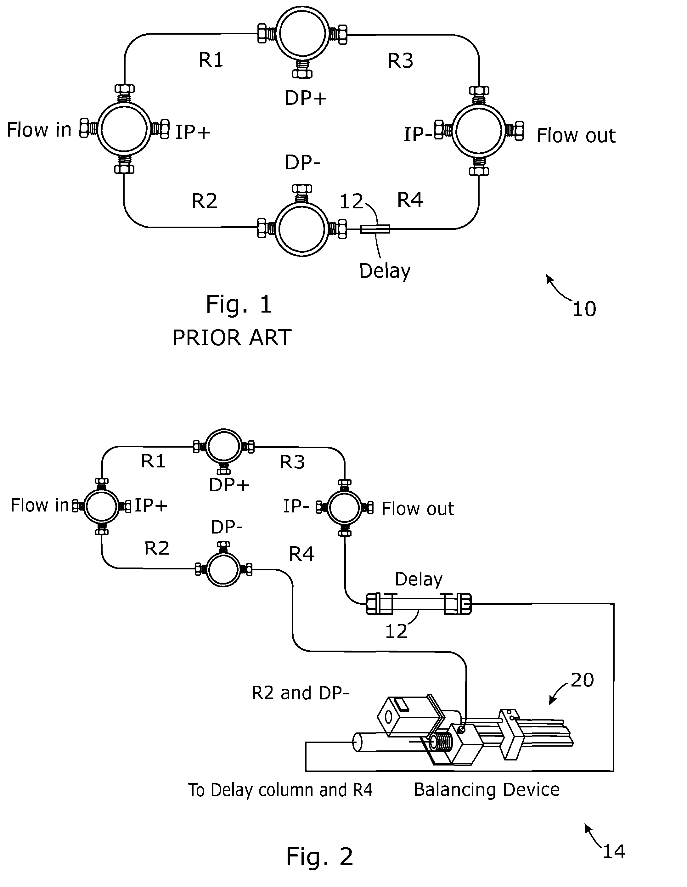
[0017]Referring to FIG. 2, an illustrative capillary bridge viscometer 14 according to the invention includes a bridge 10 with a mechanical balancing unit 20 that can be placed in series with its delay line 12. One of the capillaries is made shorter than it otherwise would at the time of assembly such that the reduction in length is approximately equal to the resistance of the mechanical balancing unit. This allows the illustrative viscometer to overcome normal changes in bridge balance it experiences.

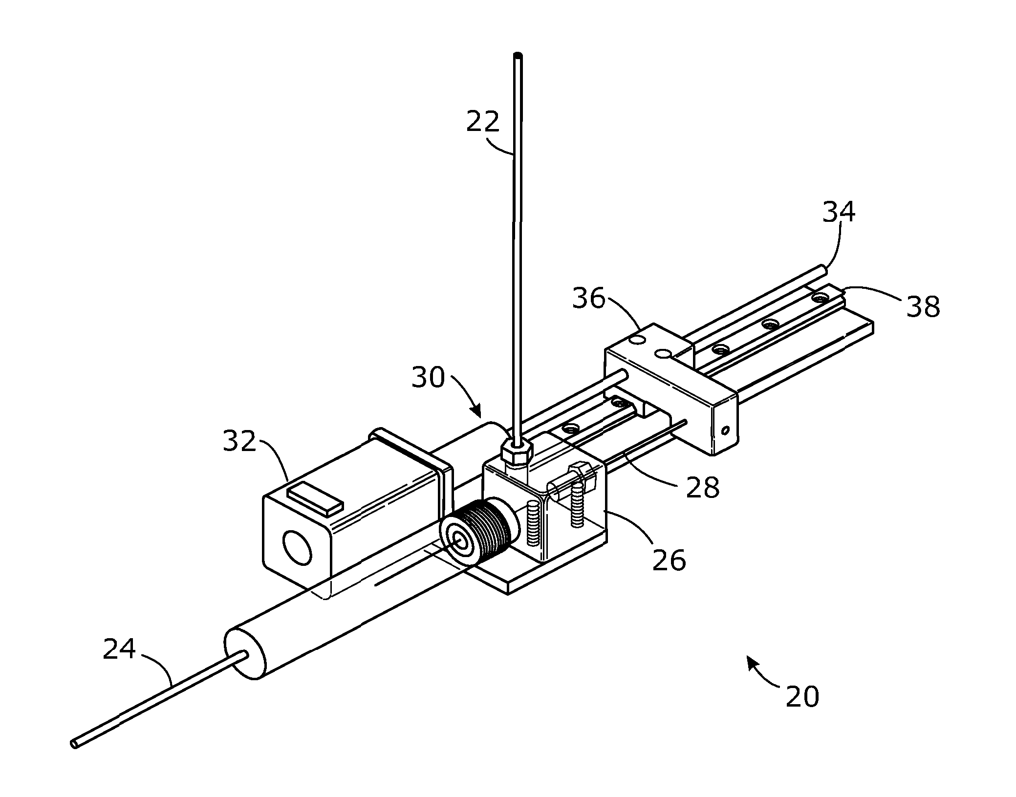
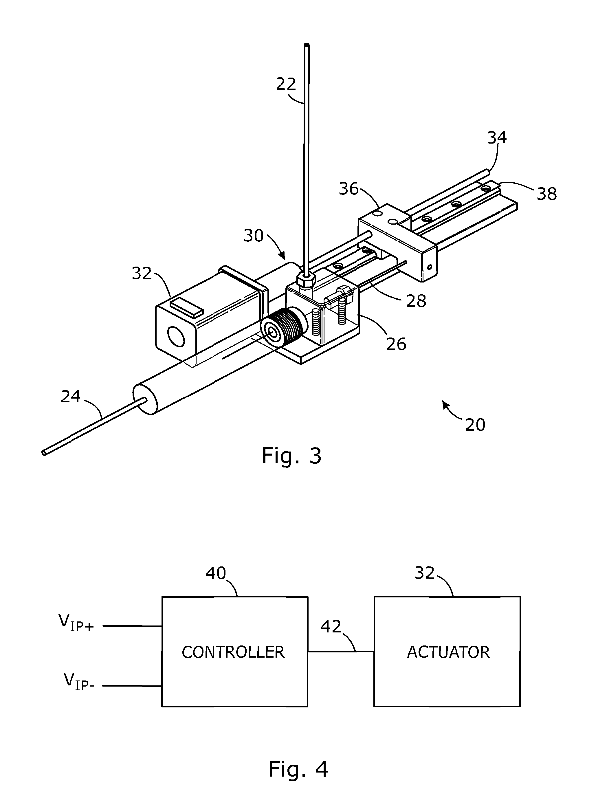
[0018]Referring to FIG. 3, the mechanical balancing unit 20 includes a first conduit 22 that is hydraulically connected to a second conduit 24, such as through a machined plumbing block 26, which can be made out of a relatively unreactive material such as stainless steel. A movable solid core 28, which can include a straight length of cylindrical Nitinol® rod, is threaded through the second conduit. This second conduit has a calculated diameter large enough to accept the core with the ...


PUM


Abstract

A capillary bridge viscometer, comprises an input port (flow in) an output port (flow out) a first capillary tubing arm (R1) in a first hydraulic path between the input port and a first differential detection point (DP+), a second capillary tubing arm (R3) in a second hydraulic path between the first differential detection point (DP+) and the output port (flow out), a third capillary tubing arm (R2) in a third hydraulic path between the input port (flow in) and a second differential detection point (DP−), a fourth capillary tubing arm (R4) in a fourth hydraulic path between the second differential detection point (DP−) and the output port (flow out), an adjustable mechanical flow restrictor (20) in one of the first, second, third, and fourth hydraulic paths, wherein the adjustable mechanical flow restrictor (20) is operative to mechanically adjust a resistance to flow of a fluid while the fluid flows through the adjustable mechanical flow restrictor.

Description

FIELD OF THE INVENTION[0001]The invention relates, in one general aspect, to capillary viscometers, including capillary bridge viscometers that include an automatic balancing mechanism.BACKGROUND OF THE INVENTION[0002]Referring to FIG. 1, multi-capillary viscometers can introduce some type of delay unit in order to make a differential measurement while a sample is being measured. An illustrative prior art four-capillary viscometer 10, for example, includes four pieces of tubing or capillaries connected in a series-parallel configuration to form the hydraulic equivalent of a Wheatstone-Bridge in electronics. These tubing or capillaries in the arms of the bridge are often referred to as R1, R2, R3, and R4 because they are in effect hydraulic resistors. The delay unit 12 is placed in series with one of the capillaries and usually it consists of a column packed with or containing a material or solvent that will delay the sample from reaching a reference capillary while a measurement is ...

Claims


Application Information

Patent Timeline
IPC IPC(8): G01N11/08
CPCG01N11/08G01N11/02G01N11/04G01N11/06G01N2011/0006G01N2011/0093G01N2011/147
Inventor NICHOLLS, MARKMURPHY, MICHAEL P.
Owner MALVERN PANALYTICAL INC
Why Eureka
Try Eureka