Conduit

a technology of conduit and splint, which is applied in the field of conduit, can solve the problems of reducing accuracy, both in pressure and timing

Inactive Publication Date: 2014-05-29
KUYPERS GILBERT JACOBUS +1
View PDF0 Cites 6 Cited by
  • Summary
  • Abstract
  • Description
  • Claims
  • Application Information

AI Technical Summary

Benefits of technology

[0078]Preferably opening of the second valve allows for delivery of (or delivers) the gases delivered to (or residing within) the communal region to the patien

Problems solved by technology

But supplying both CPAP respiratory gas and accurate delivery of a respiratory gas tidal volume to a patient has problems because the gasses a

Method used


Image

  • Conduit
  • Conduit
  • Conduit

Examples


example 1

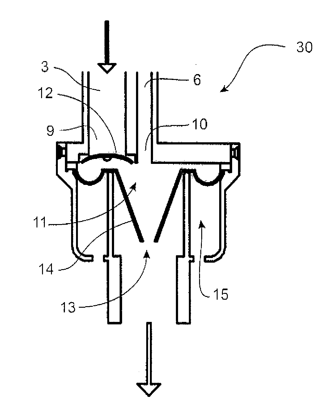
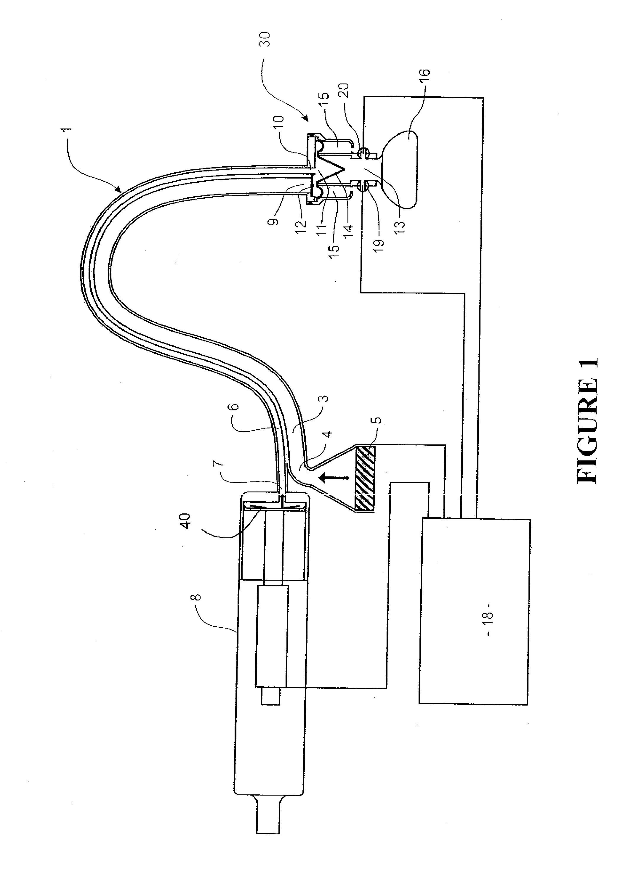
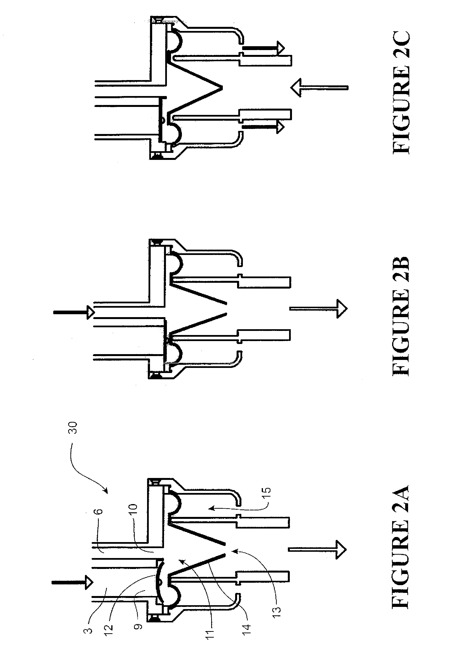
[0149]According to FIGS. 1-2C, the following is a generalised description of operation of the invention.

1. CPAP Delivery Stage: Inhalation Part of Patient Airway Cycle (FIG. 2A)

[0150]1.1 CPAP flow—a large diameter tube is used for delivery of a secondary inspiratory gas source (5) by an electrically operable blower.[0151]1.2 Large diameter tube is being used for greater control of CPAP airway pressure delivery. This is used to assist in avoiding pressure response problems.[0152]1.3 CPAP airflow pressure delivery is greater than at the end or beginning of tidal volume delivery and higher than patient airway pressure.[0153]1.4 The first valve (12) (valve for CPAP) is open.[0154]1.5 CPAP airflow pressure is then delivered through the first valve (12).[0155]1.6 The second valve (14) is open to allow gas flow through communal region (11) via the passage (13) to the patient interface (16) for delivery to a patient.[0156]1.7 Gas supply or air supplied will not flow back through the primary...

example 2

[0167]According to FIGS. 3-4C, the following is a generalised description of operation of the invention.

4. CPAP Delivery Stage: Inhalation Part of Patient Airway Cycle (FIG. 4A)

[0168]4.1 CPAP pressure is set, for example, to 5 cm H2O pressure. This pressure is set at the controller, e.g. at a control panel, and pressure is sensed and checked by a pressure sensor (19).[0169]4.2 CPAP pressure is then delivered through the larger tube of about 10 mm to 15 mm diameter via the CPAP blower device.[0170]4.3 The patient airway has a lower pressure than the set CPAP pressure (P3).[0171]4.4 The first valve (12) being a soft flexible valve made of for example, silicon, opens or is open and delivers air / oxygen to the patient through the now open second valve (14). The second valve (14) is opened by actuation of an actuator (17).

5. Tidal Volume Delivery Stage: Inhalation (FIG. 4B)

[0172]5.1 The primary inspiratory gas supplier (8) is set as an example to a pressure of 20 cm H2O and a tidal volume...


PUM


Abstract

A conduit operative or to be operative between a patient interface and both (a) a tidal volume gas delivery device that can deliver controlled tidal volume gasses to a patient for the purposes of resuscitation and (b) a CPAP device for delivery of CPAP to the patient. The conduit comprises a primary lumen having an inlet operatively connectable with said tidal volume gas delivery device. Also provides is a secondary lumen having an inlet operatively connectable with the CPAP device. A manifold, via respective outlets of the primary and secondary lumens and a manifold outlet, allows fluid communication to be established between a patient interface and both the CPAP device and the tidal volume gas delivery device.

Description

FIELD OF THE INVENTION[0001]The present invention relates to a conduit, more particularly, though not solely, to a respiratory conduit for providing inspiratory gas to a patient interface.BACKGROUND TO THE INVENTION[0002]Improvements in conduit for directing respiratory gas or gases to a patient or an interface for the patient (that is a patient interface) are continually sought after. Such conduit is widely used as part of those facilities available as a medical resource in providing respiratory gases to a patient.[0003]More specialised conduit design is employed to allow for greater control of the respiratory gases being supplied to a patient or patient interface especially where accurate tidal volume control is desired for resuscitation applications. Such accuracy being even more important for neonatal applications.[0004]In addition, providing continuous positive airway pressure (CPAP) can be useful depending on a patient's medical state or condition.[0005]Providing an improved c...

Claims


Application Information

Patent Timeline
IPC IPC(8): A61M16/20A61M16/08
CPCA61M16/0066A61M16/0072A61M16/06A61M16/0875A61M16/20A61M16/208A61M2016/0021A61M2016/0027A61M2016/0036A61M16/205
Inventor KUYPERS, GILBERT JACOBUSMCCULLOCH, RICHARD ANTHONY
Owner KUYPERS GILBERT JACOBUS
Why Eureka
Try Eureka