Hinged Panel Operation Systems and Methods

a technology of hinged panels and operation systems, applied in the direction of aircraft transmission means, aircraft power plants, transportation and packaging, etc., can solve the problems of reducing aircraft fuel consumption, reducing aircraft fuel costs, and spoilers not being able to be raised in an upward position

Inactive Publication Date: 2014-05-29
THE BOEING CO
View PDF13 Cites 25 Cited by
  • Summary
  • Abstract
  • Description
  • Claims
  • Application Information

AI Technical Summary

Benefits of technology

[0009]This need for improved systems and methods for operation of hinged panels or spoilers is satisfied. As discussed in the below detailed description, embodiments of improved systems and methods for operation of hinged panels or spoilers may provide significant advantages over known systems and methods.

Problems solved by technology

Improved efficiency and performance of aircraft takeoff and landing may result in reduced aircraft fuel consumption, and in turn, may result in reduced aircraft fuel costs.
However, on aircraft where aircraft evacuation slides may be required at the most inboard sides of the aircraft wings on overwing exits, such spoilers cannot be raised in an upward position due to the aircraft evacuation slide requirement of unobstructed aircraft slide escape paths.
However, such additional electro-mechanical actuators may increase system complexity and weight, and may result in increased installation and maintenance costs.
However, such mechanical straight linkage system of the deep hinge flap system may span a significant distance, e.g., 6 feet below the wing surface, and may thus add weight and complexity to the system, and may result in increased manufacturing and operation costs.

Method used


Image

  • Hinged Panel Operation Systems and Methods
  • Hinged Panel Operation Systems and Methods
  • Hinged Panel Operation Systems and Methods

Examples


Embodiment Construction

[0028]Disclosed embodiments will now be described more fully hereinafter with reference to the accompanying drawings, in which some, but not all of the disclosed embodiments are shown. Indeed, several different embodiments may be provided and should not be construed as limited to the embodiments set forth herein. Rather, these embodiments are provided so that this disclosure will be thorough and complete and will fully convey the scope of the disclosure to those skilled in the art.

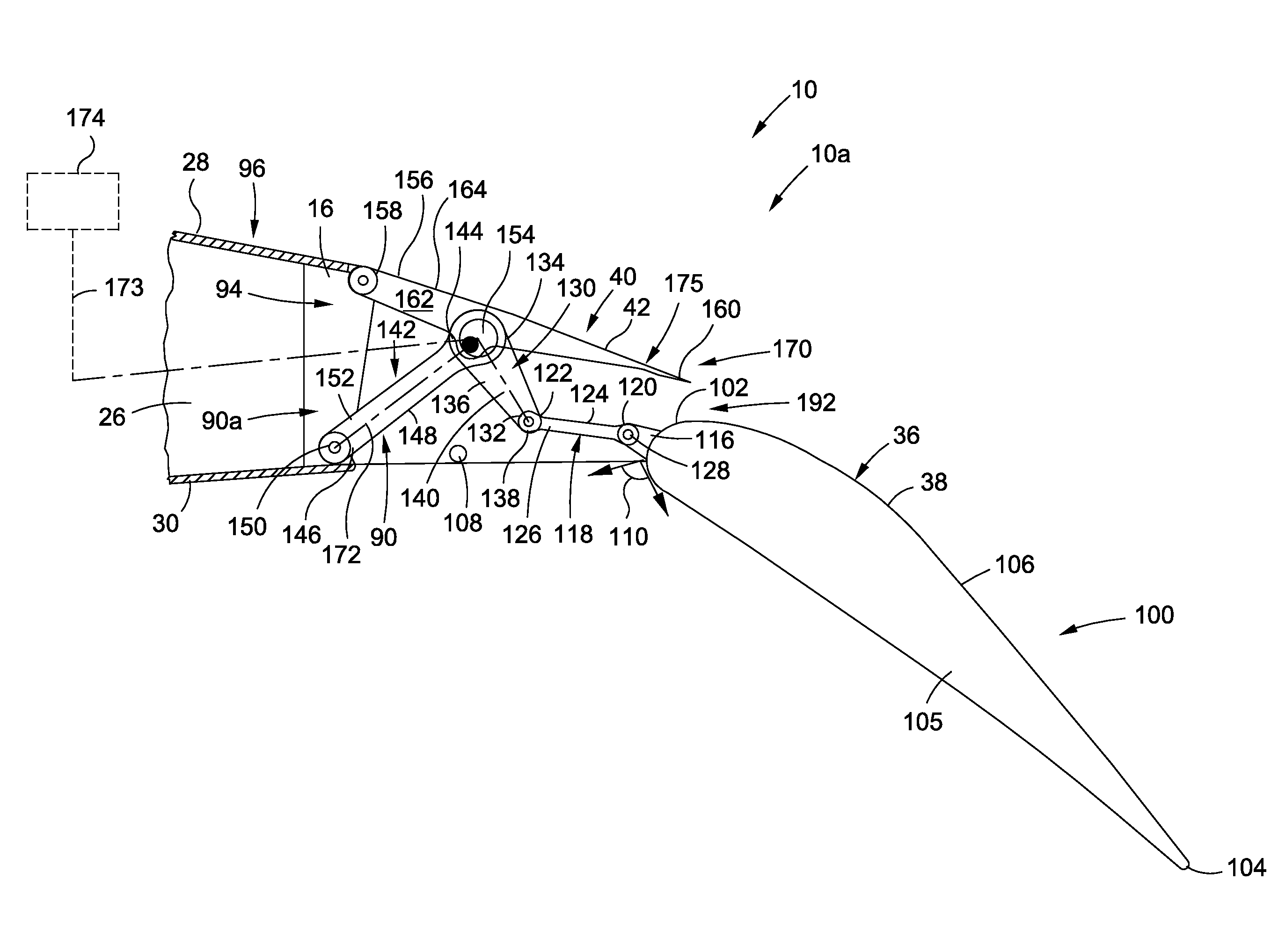
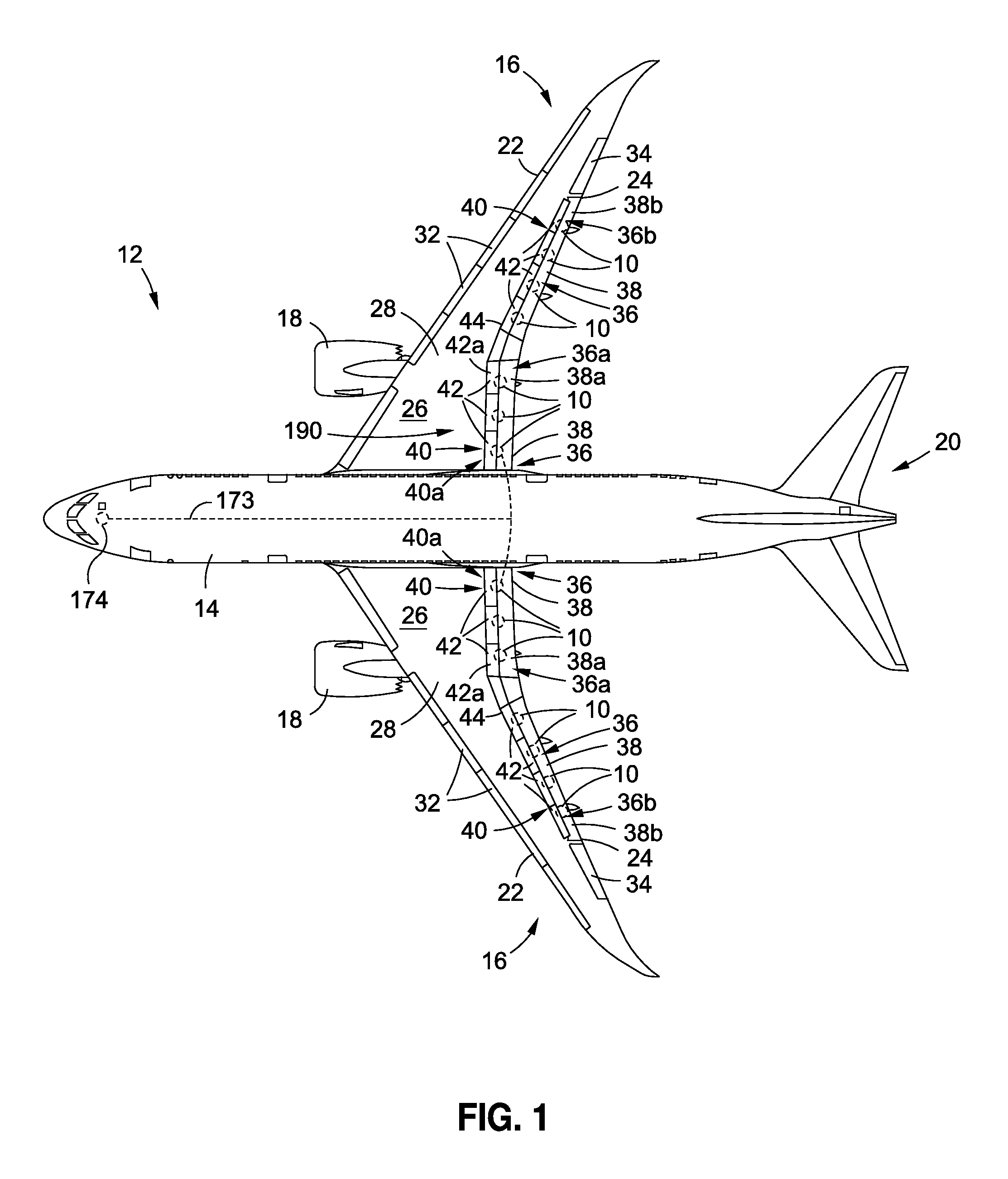
[0029]Now referring to the Figures, FIG. 1 is an illustration of a perspective view of an aircraft 12 that may incorporate one or more embodiments of a hinged panel operation system 10 of the disclosure. As shown in FIG. 1, the aircraft 12 comprises a fuselage 14, wings 16, one or more propulsion units 18, and an empennage 20. As further shown in FIG. 1, each of the wings 16 comprises a leading edge 22, a trailing edge 24, a wing body 26, a wing upper surface 28, a wing lower surface 30 (see FIG. 4A), slat...


PUM


Abstract

A hinged panel operation system is provided having a mechanical linkage assembly coupled between a fixed structure and a trailing edge device. The mechanical linkage assembly has a first link operatively coupled to the trailing edge device, a second link pivotably connected at a first end to the first link and pivotably connected at a second end to a third link, and an eccentric attachment connecting the second link to the third link. The hinged panel operation system further has a hinged panel positioned forward of the trailing edge device and being operatively coupled to the mechanical linkage assembly. The hinged panel is movable by the mechanical linkage assembly between a stowed position and a drooped position. The mechanical linkage assembly provides a load path to the hinged panel.

Description

BACKGROUND[0001]1) Field of the Disclosure[0002]The disclosure relates generally to systems and methods for operation of hinged panels and spoilers, and more specifically, to systems and methods for operation of hinged panels and spoilers for aircraft, including aircraft hinged panel and spoiler droop systems and methods.[0003]2) Description of Related Art[0004]The wings of high-speed transport vehicles, such as aircraft or other air vehicles, typically include various movable surfaces or devices to provide aircraft control and / or to configure the aircraft for low speed operations, such as aircraft takeoff and landing. Such movable surfaces or devices may include, for example, leading edge devices, such as flaps and slats, and trailing edge devices, such as hinged panels or spoilers, flaps, and ailerons. These movable surfaces or devices are typically movable between a stowed position and a variety of deployed or extended positions, depending upon the particular flight condition of ...

Claims


Application Information

Patent Timeline
Patent Type & Authority Applications(United States)
IPC IPC(8): B64C13/28B64C9/02
CPCB64C9/02B64C13/28B64C9/10B64C9/16Y02T50/30Y02T50/40
Inventor BEYER, KEVIN W.SAKURAI, SEIYASTEPHENSON, MARTIN F.
Owner THE BOEING CO
Why Eureka
Try Eureka