Lock ring mounting/demounting jig

Active Publication Date: 2014-06-05
TOPY INDUSTRIES
View PDF2 Cites 1 Cited by
  • Summary
  • Abstract
  • Description
  • Claims
  • Application Information

AI Technical Summary

Benefits of technology

The invention is a lock ring assembly for a tire that includes a lock ring and gutter band. The lock ring has protrusions that fit into grooves on the gutter band to secure the tire. The lock ring is mounted on a lock ring holder using jigs that can expand or contract to ensure the lock ring is securely mounted without being dislodged during use. The jigs are designed to expand or contract by rotating an expansion member, which allows for easy and safe mounting of the lock ring without needing to hold it in place while resisting its elastic repulsion force. This eliminates the need for a worker to carry out a difficult and labor-intensive job while also ensuring the lock ring is securely mounted. The invention simplifies the process of mounting and demounting the lock ring, making it easier and safer for workers.

Problems solved by technology

The tire for use in the large-sized construction machine or mining machine differs in rigidity from a tire for use in a passenger car, so that the tire for use in the large-sized construction machine or mining machine does not fit into a single-piece rim on many occasions.
Herein, since there is the case where the lock ring 4 has a mass as large as, for example, on the order of 50 kg, it is extremely difficult to hold the lock ring 4 so heavy in weight while resisting the elastic repulsion force urging the contraction in the radial direction and to dispose the same at a predetermined position, and excessive labor will be required.
Such prior art can be useful, however, it does not eliminate a problem associated with mounting / demounting of the lock ring, described as above.Patent Publication 1: JP-A No. 2000-108603

Method used


Image

  • Lock ring mounting/demounting jig
  • Lock ring mounting/demounting jig
  • Lock ring mounting/demounting jig

Examples


first embodiment

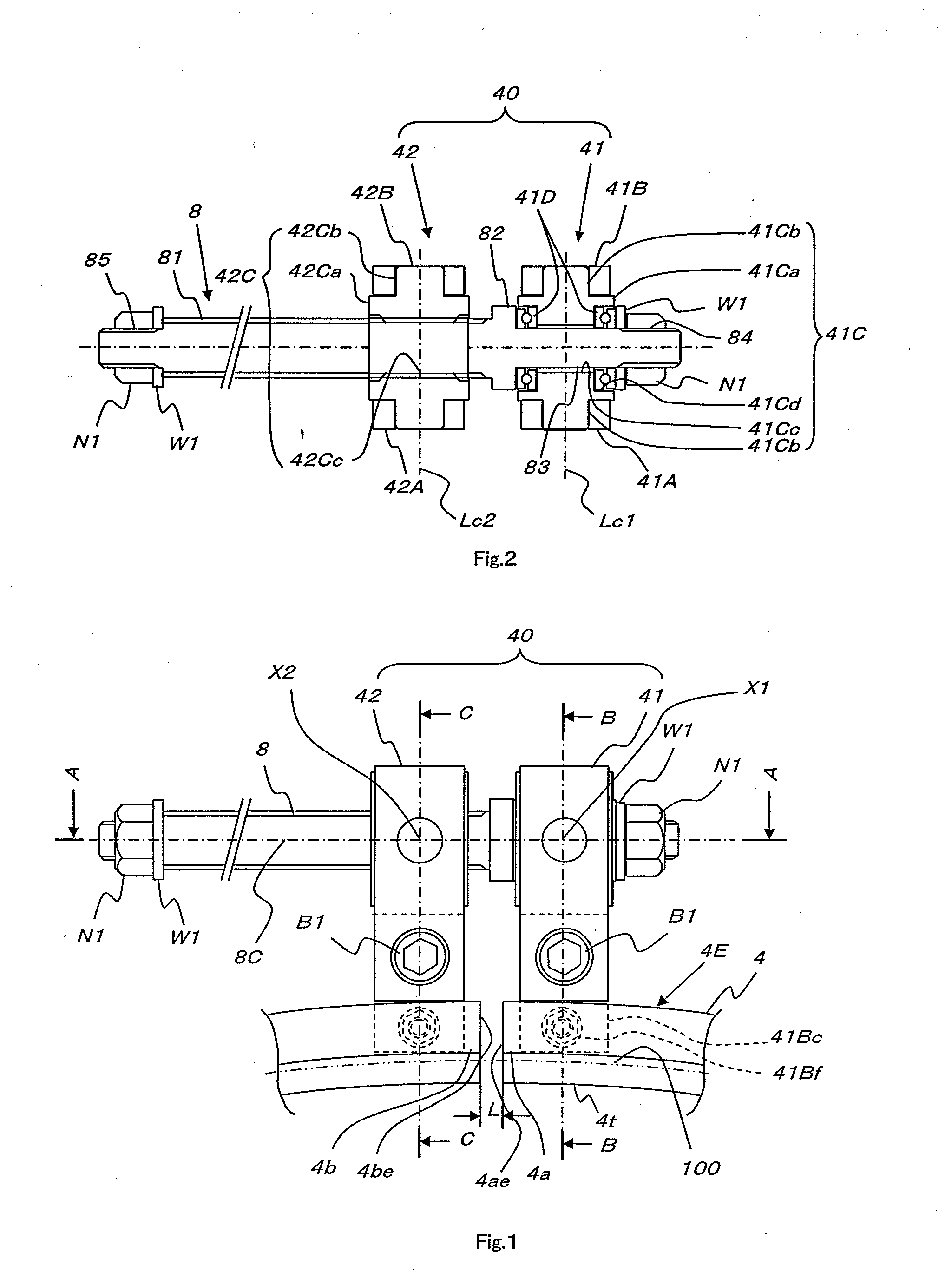
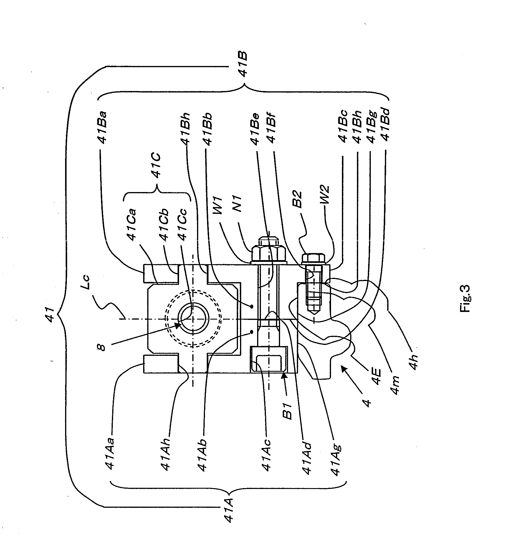
[0117]With the first embodiment having such a construction as described in the foregoing, since the jigs 41, 42 in pairs, mounted on the respective ends 4a, 4b of the lock ring 4 are constructed such that the space between the pair of jigs is expandable, it is possible to maintain with ease and certainty a state where the inside diameter ΦD1 of the lock ring 4 (the inside diameter of the lock ring 4 at the apex of the protrusion 4t) is larger than the outside diameter ΦD2 of the gutter band 11 at the time of mounting and demounting the lock ring 4.

[0118]Therefore, upon mounting of the lock ring 4, if the jigs 41, 42 in pairs mounted on the ends 4a, 4b of the lock ring are parted further from each other by turning the screw bolt 8 while resisting elastic repulsion force of the jig 40, urging contraction in the radial direction thereof, it is possible to increase the distance L between respective end faces 4ae, 4be of the lock ring (4) and to maintain with ease and certainty the state...

second embodiment

[0140]Next, there is described hereinafter the invention with reference to FIGS. 14 to 18.

[0141]FIG. 14 shows the overview of the second embodiment of the invention.

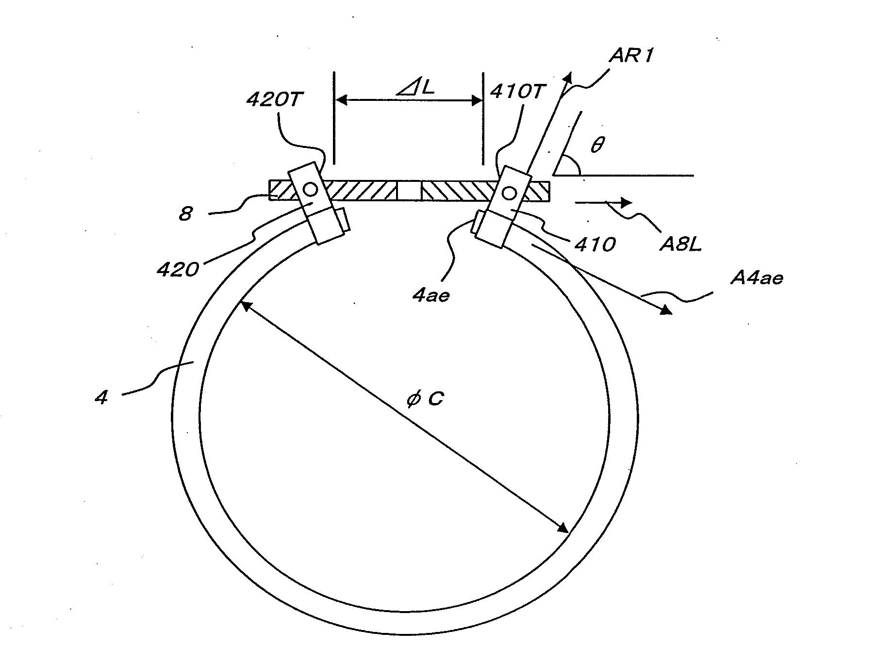
[0142]As shown in FIG. 14, in the second embodiment, jigs 410, 420, fixedly attached to respective ends of a lock ring 4, are made up such that angles (in FIG. 14, an angle θ is shown by way of example) which respective ends 410T, 420T of the jigs 410, 420 form with a center axis A8L of a screw bolt 8 are freely variable.

[0143]Accordingly, in FIG. 14, although the screw bolt 8 is in mesh with the jigs 410, 420, respectively, as a space ΔL between the jigs 410, 420 becomes ether wider, or narrower, so the angles which the respective ends 41T, 42T form with the center axis A8L are gradually changed. Then, occurrence of abrupt variation in curvature at parts of the lock ring 4, in close proximity to the jigs 410, 420, respectively, is prevented.

[0144]As a result, a direction (the direction of the arrow A4ae) of the tangent ...


PUM

PropertyMeasurementUnit
Fractionaaaaaaaaaa
Weightaaaaaaaaaa
Angleaaaaaaaaaa

Abstract

An object of the present invention is to provide a jig that does not require an operator to hold a lock ring against the elastic repulsion force of the lock ring that attempts to contract in a radial direction when the lock ring is attached to a rim base, the jig that is safe because there is no need for the operator to support the weight of the lock ring and can maintain a state in which, when the space between the ends of the lock ring is increased, the inside diameter side of the lock ring is a perfect circle or is close to a perfect circle. Thus, a lock ring mounting / demounting jig of the present invention is formed of a pair of jigs, the pair of jigs can be attached at both ends (4a, 4b) of a lock ring (4) and on the radial outside of the lock ring (4), and the angle formed by the direction in which the space between the pair of jigs expands and contracts and the longitudinal direction of each jig is changeable.

Description

CROSS REFERENCE TO RELATED APPLICATIONS[0001]This application is a continuation-in-part (CIP) application of U.S. patent application Ser. No. 12 / 673,732 filed on Feb. 16, 2010 and that application is the National Stage of International Application No. PCT / JP / 2008 / 64519, filed on Aug. 13, 2008. Therefore, it is believed that this continuation-in-part application is copending with the prior application. The disclosures of U.S. patent application Ser. No. 12 / 673,732 and International Application No. PCT / JP / 2008 / 64519 are hereby incorporated by reference.TECHNICAL FIELD[0002]The present invention relates to a multi-piece rim to be fitted to a tire for use in a construction machine or mining machine, and particularly, a multi-piece rim to be fitted to a tire for use in a large-sized construction machine or mining machine.BACKGROUND ART[0003]The tire for use in the large-sized construction machine or mining machine differs in rigidity from a tire for use in a passenger car, so that the ti...

Claims


Application Information

Patent Timeline
IPC IPC(8): B60B25/04
CPCB60B25/04B60B25/20Y10T29/53657
Inventor OBA, KENTARONAKAMURA, YUKIOSUGISAKI, ETSURO
Owner TOPY INDUSTRIES
Why Eureka
Try Eureka