System for supplying direct electric power for at least two loads from an alternating electric power source and method for starting such a supply system

Active Publication Date: 2014-06-05
SCHNEIDER ELECTRIC IND SAS
View PDF1 Cites 0 Cited by
  • Summary
  • Abstract
  • Description
  • Claims
  • Application Information

AI Technical Summary

Benefits of technology

The patent describes a way to control the connection between two devices, which allows for the immediate supply of power between them. This control means can also shift the time when the power is supplied, making it more flexible and efficient.

Problems solved by technology

Starting an installation for supplying direct electric power, or restarting it for example after power has been cut, is not without problems.
In fact, each load needs time to charge its capacitances, which is often different from one mode to another and delays the start-up of the load.
Starting or restarting such an installation may then take several hours.

Method used


Image

  • System for supplying direct electric power for at least two loads from an alternating electric power source and method for starting such a supply system
  • System for supplying direct electric power for at least two loads from an alternating electric power source and method for starting such a supply system
  • System for supplying direct electric power for at least two loads from an alternating electric power source and method for starting such a supply system

Examples


second embodiment

[0070] the power supply system 10 comprises two circulation loops 14A, 14B for the alternating electric power, each loop being capable of being connected to a respective alternating electric power source 12A, 12B, the or each converter 16 being connected to the two circulation loops by toroids 18. The loop 14A is connected to the AC source 12A. The loop 14B is connected to the AC source 12B.

[0071]The operation of the second embodiment is similar to that of the first embodiment previously described, and will not be described again.

[0072]The advantages of the second embodiment are similar to those of the first embodiment previously described. The second embodiment further allows redundancy, each converter 16 being connected to two current sources 12A, 12B.

[0073]FIG. 6 illustrates a third embodiment of the invention in which the elements similar to the first embodiment, previously described, are identified using identical references, and are not described again.

third embodiment

[0074] the power supply system 10 is connected to an alternating voltage source 38. A circulation bus 40 for the alternating electric power is connected to the alternating voltage source 38. Converters 16 are connected to the voltage bus 40 by voltage transformers 42.

[0075]The operation of this third embodiment is similar to that of the first embodiment previously described, and is not described again.

[0076]The advantages of this third embodiment are similar to those of the first embodiment previously described.

[0077]FIG. 7 illustrates a fourth embodiment of the invention for which the elements similar to the first embodiment, previously described, are identified using identical references, and are not described again.

fourth embodiment

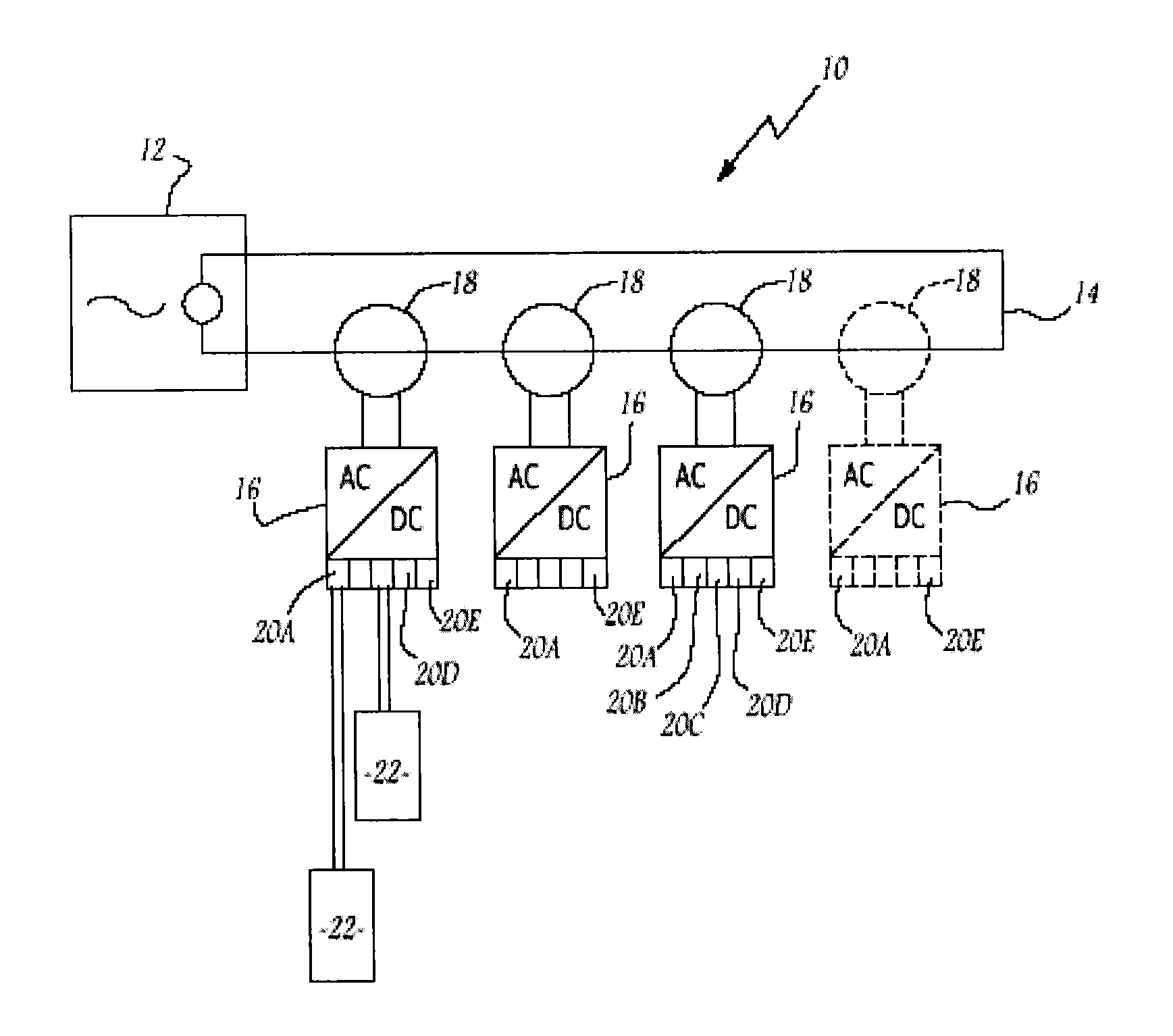
[0078] the converters 16 include connection interfaces 20A, . . . , 20E adapted to be connected to multiple loads 22 via a current bar 44.

[0079]All of the loads 22 connected to that current bar 44 start up at the same time, i.e., after expiration of the time delay selected for the connection interface 20A, . . . , 20E to which the current bar 44 is connected. It therefore suffices to connect all of the devices that must start up at the same time to the shared current bar 44.

[0080]Such a power supply system 10 is for example advantageous for a water distribution installation with Ethernet communications between different servers and Profibus and ADC communications that control the pumps with electric motors supplied with direct voltage and electrically controlled valves.

[0081]Another example of an installation in which such a power supply system 10 is advantageous is an intelligent power and motor control center (iPMCC).

[0082]The loads 22 powered by this power supply system 10 are fo...


PUM


Abstract

The invention relates to a system for supplying direct electric power to at least two loads from an alternating electric power source comprises a circulation bus for the alternating power adapted to be connected to the alternating power source and at least one converter for converting alternating power into direct power, connected to the circulation bus.The system further comprises at least two connection interfaces, each connection interface being connected to a corresponding converter and being adapted to be connected to at least one electric load to supply direct electric power for the or each corresponding load; and means for controlling the connection interfaces, the control means being capable of time-shifting the start-up moment for the supply of direct power from one interface to the other.

Description

BACKGROUND OF THE INVENTION[0001]The present invention relates to a system for supplying direct electric power for at least two loads from an alternating electric power source. The system comprises a circulation bus for the alternating electric power adapted to be connected to the alternating electric power source and at least one AC-DC converter, connected to the circulation bus.[0002]The present invention also relates to a method for starting up such a system for supplying direct electric power for at least two loads.[0003]Starting an installation for supplying direct electric power, or restarting it for example after power has been cut, is not without problems. In fact, each load needs time to charge its capacitances, which is often different from one mode to another and delays the start-up of the load.[0004]The loads are for example communication switches, gateways, machines, data servers, and protective devices.[0005]To correctly start or restart such an installation, there is ...

Claims


Application Information

Patent Timeline
IPC IPC(8): H02J1/00
CPCH02J1/00H02J5/00H02J2310/12H02J3/14Y02B70/3225Y04S20/222Y02P80/14
Inventor MEYSENC, LUCBARSTZ, DANIELWATERLOT, FREDERIC
Owner SCHNEIDER ELECTRIC IND SAS
Why Eureka
Try Eureka