Harmonic rejection power amplifier

a power amplifier and harmonic rejection technology, applied in the field of power amplifiers, can solve the problems of reducing the effect of the reduction of odd harmonics, the shift of timing signals, etc., and achieve the effect of reducing harmonics and increasing the influence of time delay due to devices or interconnection

Inactive Publication Date: 2016-07-19
PANASONIC CORP
View PDF10 Cites 0 Cited by
  • Summary
  • Abstract
  • Description
  • Claims
  • Application Information

AI Technical Summary

Benefits of technology

[0009]The power amplifier of FIG. 13, however, requires a timing generator circuit that generates a plurality of timing signals A10, B10, and C10 having the different duty ratios in order to reduce the harmonics. As disclosed in International Publication No. 2008 / 032782, the timing generator circuit is a circuit having a logic circuit in which AND circuits and OR circuits are combined, for instance. As frequencies of the signals are increased in the timing generator circuit, therefore, influence of time delay due to devices or interconnection is increased and timing of rise and fall of the timing signals is shifted from ideal thereof. Thus, the power amplifier of FIG. 13 has a problem in that the shift of the timing signals reduces an effect of the reduction in the odd harmonics.
[0010]One non-limiting and exemplary embodiment provides a power amplifier that is capable of reducing odd harmonics with facility even on condition of high frequencies.
[0013]According to the disclosure, the duty ratios of the n timing signals are equalized and thus the odd harmonics can be reduced with facility even on condition of high frequencies.

Problems solved by technology

Thus, the power amplifier of FIG. 13 has a problem in that the shift of the timing signals reduces an effect of the reduction in the odd harmonics.

Method used


Image

  • Harmonic rejection power amplifier
  • Harmonic rejection power amplifier
  • Harmonic rejection power amplifier

Examples


first embodiment

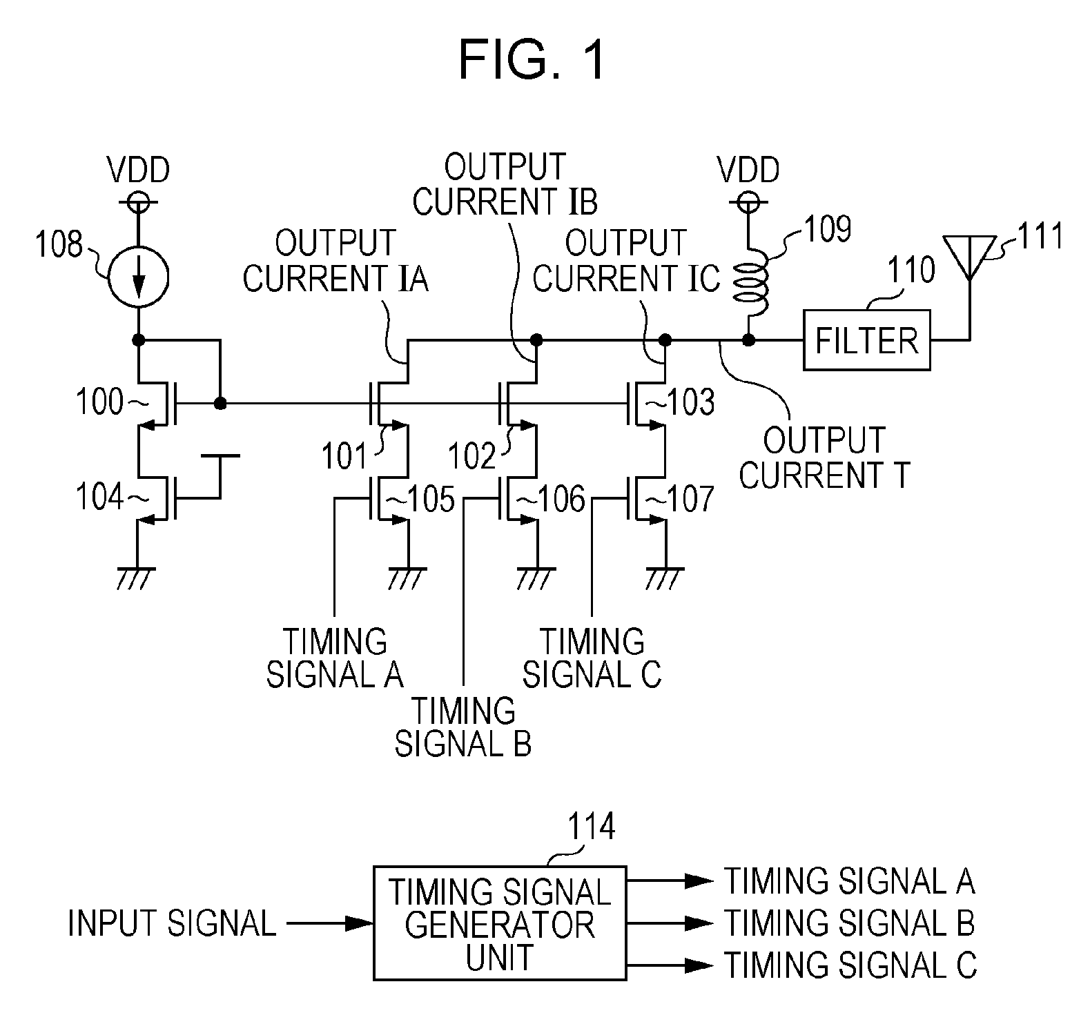
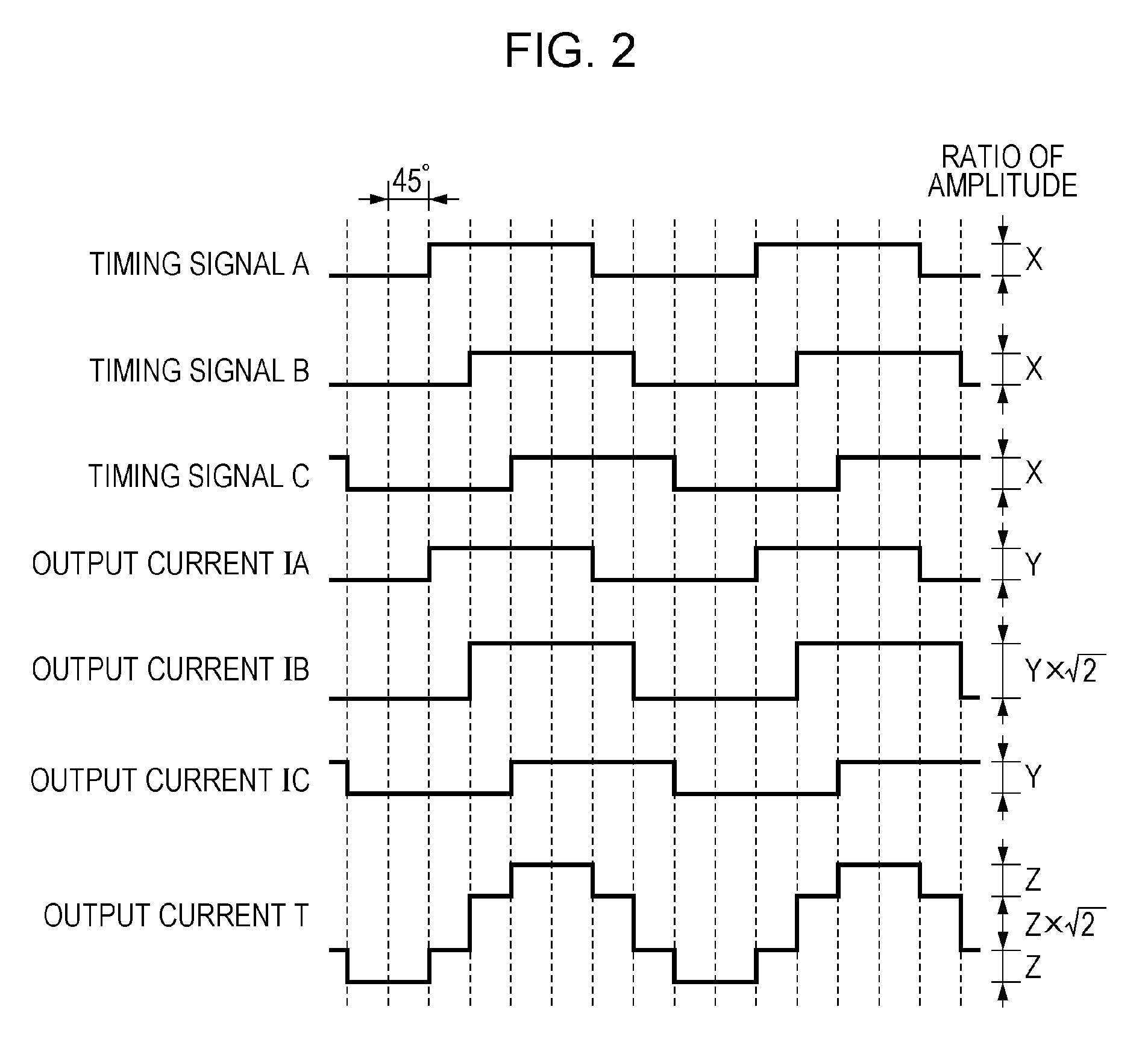
[0030]FIG. 1 illustrates a configuration of a power amplifier according to a first embodiment of the disclosure. The power amplifier according to the first embodiment is a harmonic rejection power amplifier that reduces harmonics.

[0031]In FIG. 1, the power amplifier according to the first embodiment includes a reference current source 108, a plurality of N-channel metal-oxide-semiconductor field-effect transistors (NMOS transistors) 100 through 103 that constitute current mirror circuits, a plurality of NMOS transistors 104 through 107 as switches, a coil 109 for pull-up, a band-pass filter 110, and a timing signal generator unit 114 as a generator unit. The power amplifier, of which an output terminal is connected to an antenna 111, outputs a current with large amplitude to the antenna 111.

[0032]In FIG. 1, the reference current source 108 and the NMOS transistors 100, 101, 102, and 103 constitute the current mirror circuits. The reference current source 108 is a constant current so...

second embodiment

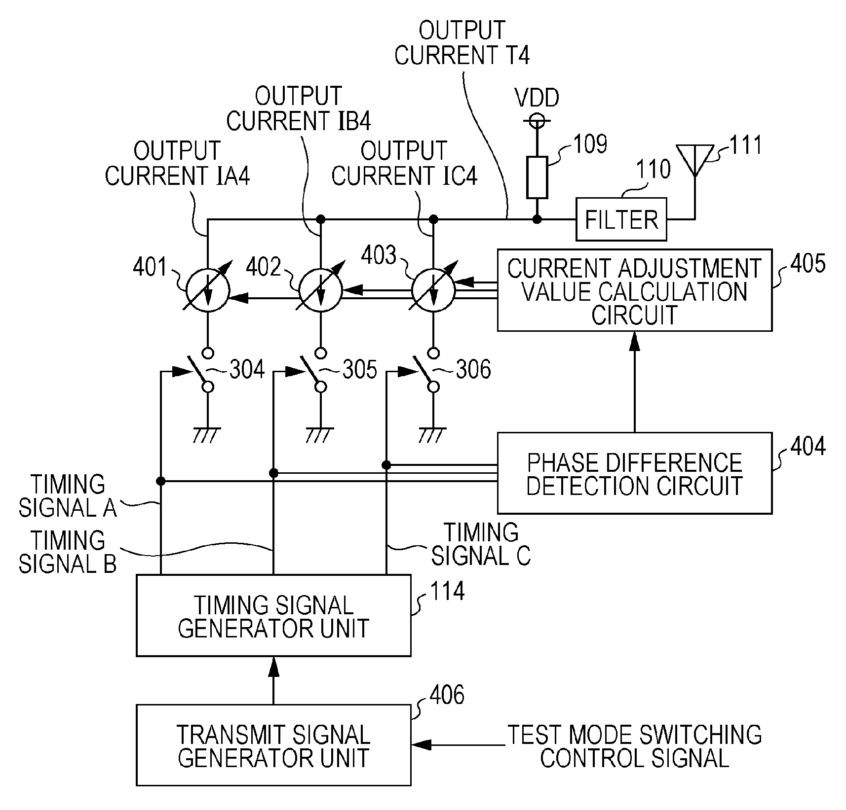
[0055]FIG. 6 is a conceptual diagram illustrating a power amplifier according to a second embodiment of the disclosure. In FIG. 6, the same reference characters as those in FIG. 3 are used for components similar to those in FIG. 3 and description thereon is omitted.

[0056]As illustrated in FIG. 6, the power amplifier according to the second embodiment includes constant current sources 401, 402, and 403 in place of the current sources 301, 302, and 303 illustrated in FIG. 3. In addition to a configuration similar to that in FIG. 3, the power amplifier includes a phase difference detection circuit 404 as a detection unit, a current adjustment value calculation circuit 405 as a calculation unit, and a transmit signal generator unit 406, as illustrated in FIG. 6.

[0057]The constant current sources 401, 402, and 403 are configured so that ratio of currents flowing through the constant current sources 401, 402, and 403 may be 1:21 / 2:1, as in the first embodiment. In the constant current sou...


PUM


Abstract

A power amplifier is provided that generates timing signals which respectively turn on or off switches for respectively opening or closing current paths for current sources and which have same duty ratio and different phases and that adjusts current values for the current sources based on phase differences among the timing signals.

Description

BACKGROUND[0001]1. Technical Field[0002]The present disclosure relates to a power amplifier.[0003]2. Description of the Related Art[0004]There is a power amplifier as a circuit that outputs signals of which amplitude has been amplified for emission of radio waves from an antenna, for instance.[0005]As the power amplifier, as illustrated in FIG. 11, a circuit which is composed of an N-channel MOS transistor 801, an inductor 802, and a band-pass filter 803 and in which pulse waves are used as input signals is widely used. In this configuration, however, output of the power amplifier has a waveform similar to the input pulse and includes harmonics.[0006]Apart from FIG. 11, there is a pulse-type power amplifier using an inverter that is composed of an N-channel MOS transistor 902 and a P-channel MOS transistor 901, as illustrated in FIG. 12. In this configuration as well, harmonics are generated in output.[0007]In the past, a power amplifier that synthesizes output of a plurality of amp...

Claims


Application Information

Patent Timeline
Patent Type & Authority Patents(United States)
IPC IPC(8): H03F1/30H03F3/72H03F3/217H03F1/02H03F3/21H03F3/24H03F1/22H03F3/195
CPCH03F1/0277H03F1/223H03F3/195H03F3/211H03F3/2176H03F3/245H03F3/72H03F2200/171H03F2200/451H03F2203/7215
Inventor OKADA, EIJI
Owner PANASONIC CORP
Why Eureka
Try Eureka