
System and Method for Wide Area Motion Imagery

a wide-area motion imaging and tracking system technology, applied in the field of airborne surveillance and tracking systems, can solve the problems of large-scale raw data transmission from the aircraft to the ground station, large-scale raw data transmission link is not readily available, satellite capacity, i.e. bandwidth, for relaying such signals, is often either limited or extremely expensive, so as to reduce the amount of data and increase the effect of computer power requirements

Inactive Publication Date: 2014-06-05
TACHYON NETWORKS
View PDF0 Cites 10 Cited by
  • Summary
  • Abstract
  • Description
  • Claims
  • Application Information

AI Technical Summary

Benefits of technology

The present invention is a system for detecting moving objects in a specific area. The system is designed to reduce the amount of data required for transmitting information of object movement from an airborne surveillance platform to a ground-based operator station. This is achieved by increasing computer power requirements on the surveillance platform and performing geo-registration to align two-dimensional images with three-dimensional models, which helps to better detect object movements. Only the tracking data that needs to be transmitted to a ground-based operator station is sent, which can be easily evaluated using the provided three-dimensional model. Overall, the system is efficient in detecting moving objects and reducing data requirements.

Problems solved by technology

It happens that the real-time transmission of this large amount of raw data from the aircraft to a ground station requires a large bandwidth link.
In some cases, a large bandwidth transmission link is not readily available.
Satellite capacity, i.e. bandwidth, for relaying such signals, is often either limited or extremely expensive.
For these reasons, real-time transmission of raw image data during BLOS surveillance missions is often infeasible.

Method used


Image

  • System and Method for Wide Area Motion Imagery
  • System and Method for Wide Area Motion Imagery
  • System and Method for Wide Area Motion Imagery

Examples


Embodiment Construction

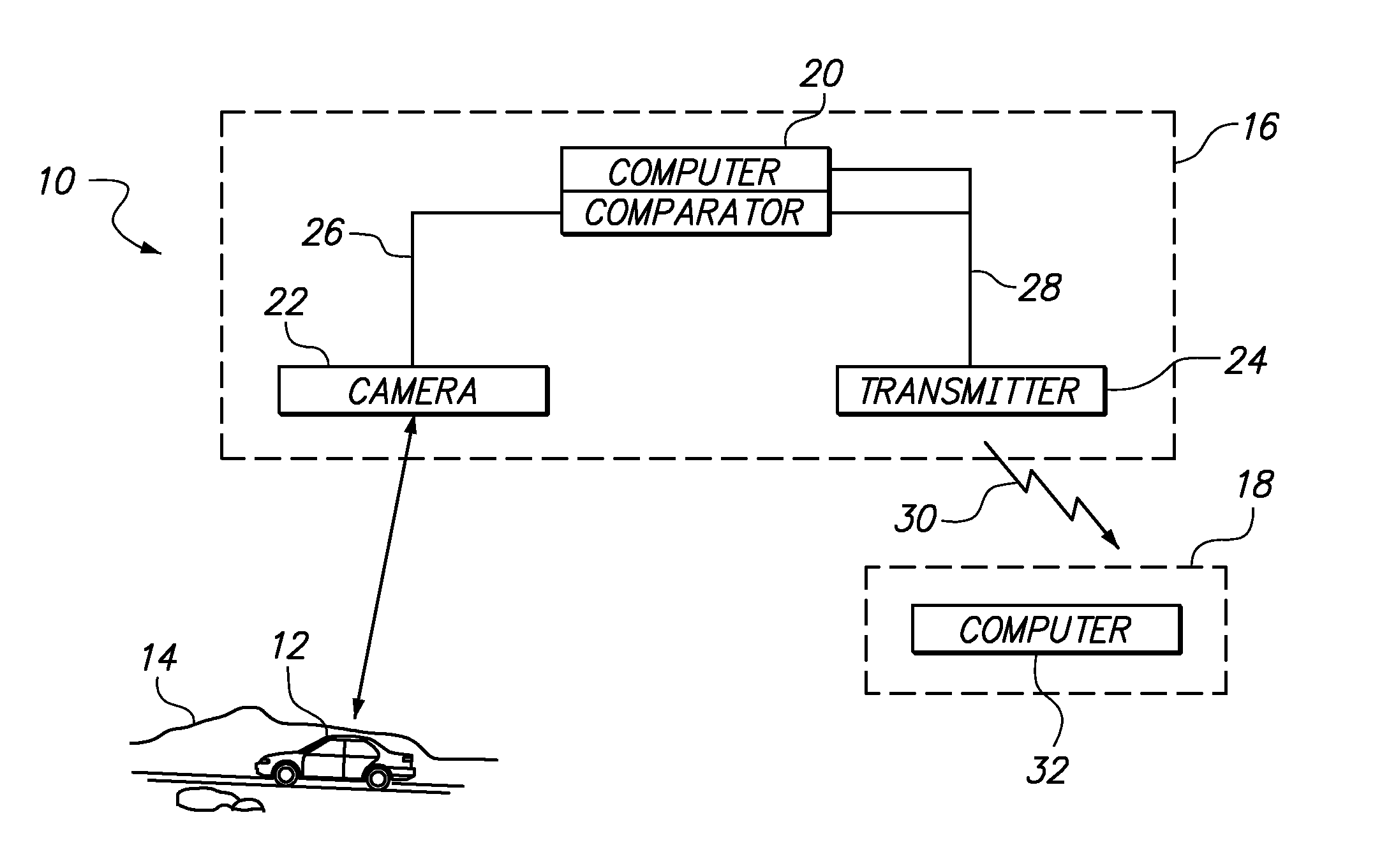
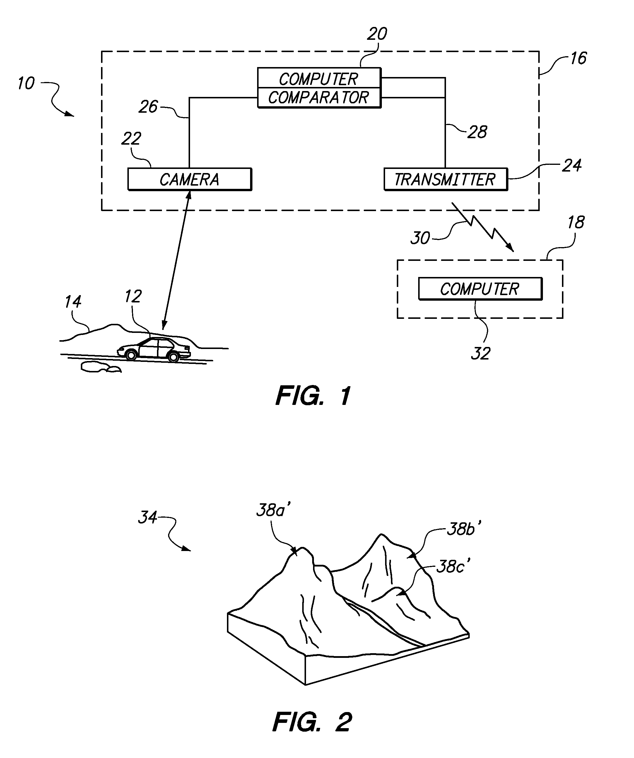
[0021]With initial reference to FIG. 1, a system for wide area motion imagery is shown and generally designated 10. As shown, the system 10 can function to detect and / or track a moving object 12, such as a vehicle on the ground 14. FIG. 1 further shows that the system 10 includes an airborne surveillance platform 16 for creating surveillance image(s), processing imagery data and transmitting data to a ground-based operator station 18.

[0022]In more structural detail, FIG. 1 shows that constituents of the system 10 on the surveillance platform 16 include a computer / comparator 20, one or more sensors 22, such as one or more cameras, and a transmitter 24. During a surveillance mission, the surveillance platform 16, which is typically an aircraft, is flown over a preselected area. Once over the preselected area, the sensor 22 is used to collect raw imagery data that is transmitted to the computer / comparator 20 via electrical connection 26. The raw data is then processed by the computer / c...


PUM


Abstract

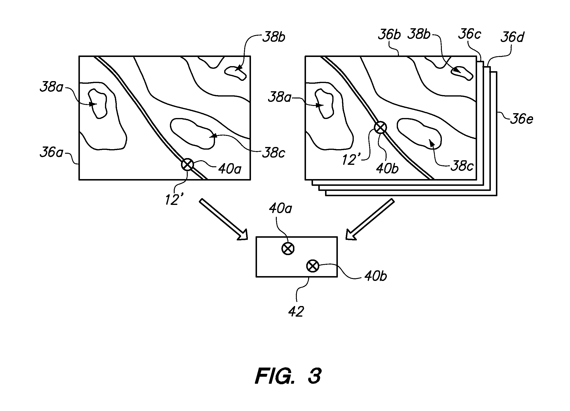
A system for detecting moving objects within a predetermined geographical area is provided. The system is designed to convey object movement information from an airborne surveillance platform to a ground-based operator station with reduced data transmission. This is accomplished by computer processing image data on the surveillance platform prior to transmitting data to the ground station. First, the system constructs a 3D model of the area under surveillance, for example, by obtaining many different views of the area using an aircraft. One 3D model is maintained at the surveillance platform, and another is transmitted to the ground station. During a surveillance mission, a succession of relatively low data, 2D images are created and aligned with the surveillance platform's 3D model. The alignment reveals differences in the images (tracking data) which is then transmitted to the ground station for use with the ground station's 3D model to resolve object movement information.

Description

[0001]This application claims the benefit of U.S. Provisional Patent Application Ser. No. 61 / 721,268, entitled SYSTEM AND METHOD FOR WIDE AREA MOTION IMAGERY, filed Nov. 1, 2012. The entire contents of Application Ser. No. 61 / 721,268 are hereby incorporated by reference herein.FIELD OF THE INVENTION[0002]The present invention pertains generally to airborne surveillance and tracking systems. More particularly, the present invention pertains to systems and methods for transmitting surveillance and tracking data from an airborne platform to a ground-based operator station. The present invention is particularly, but not exclusively, useful for effectively and efficiently transmitting image information over a beyond-line-of-sight (BLOS) communication channel having at least one relatively low bandwidth link.BACKGROUND OF THE INVENTION[0003]During surveillance missions, the goal is typically to spot interesting activity on the ground. These missions generally generate large amounts of raw...

Claims


Application Information

Patent Timeline
IPC IPC(8): H04N7/18H04N13/02
CPCH04N13/02H04N7/185
Inventor CARIDES, PETER ALEXANDERROBBINS, BARRY R.SINGH, DILRAJDICKHOVEN, SIMON H.
Owner TACHYON NETWORKS
Learn More