

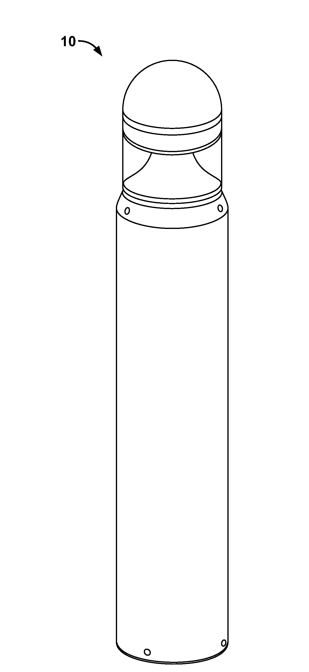
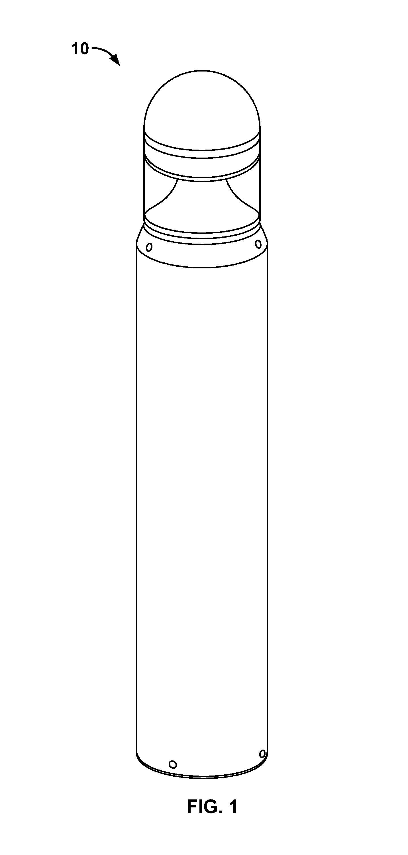
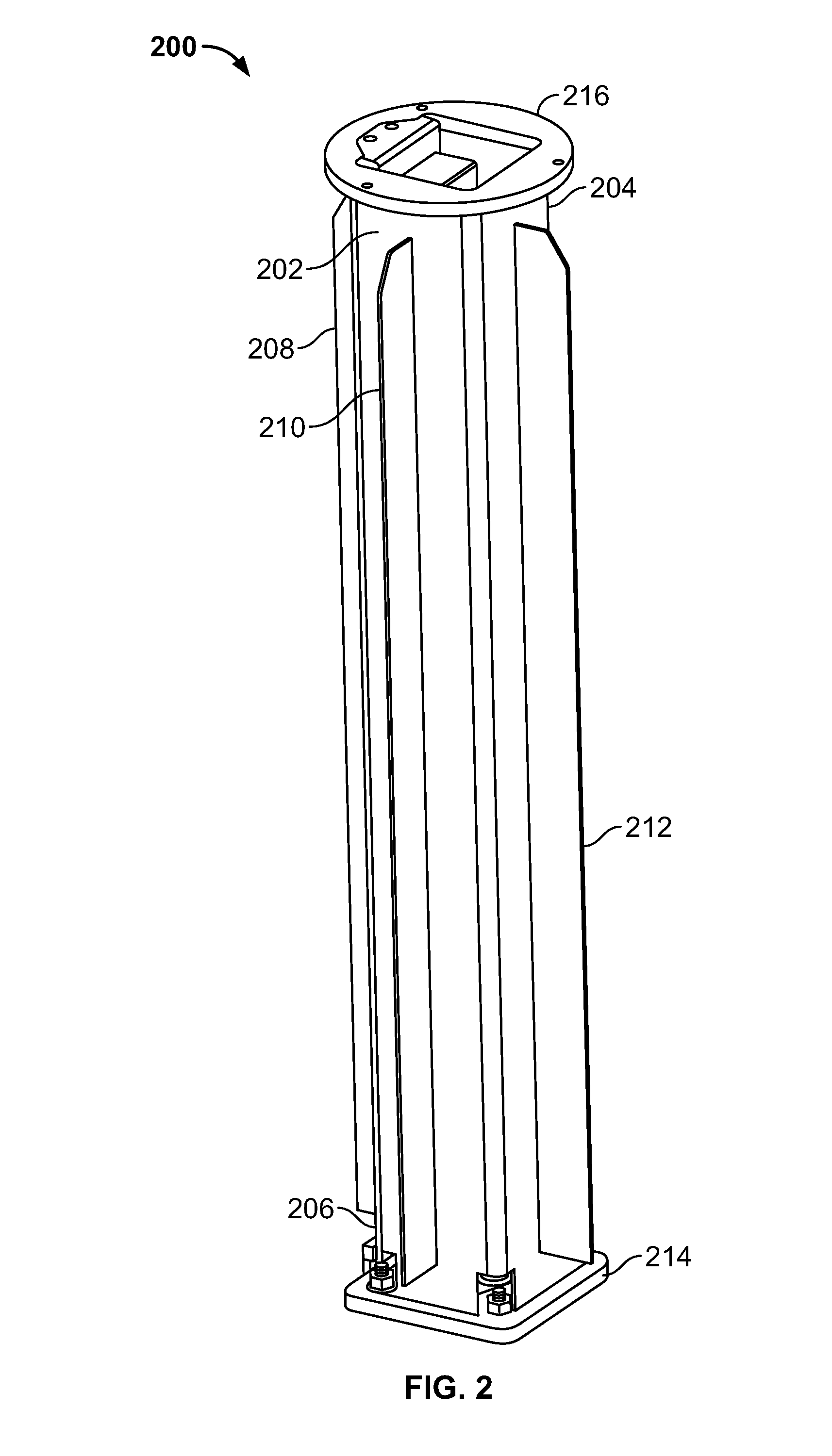
Bollard light with internal compression support system
a technology of internal compression and support system, which is applied in the direction of lighting support devices, lighting and heating apparatus, and ways, etc., can solve the problems of increased construction cost, increased construction cost, and increased construction cost, and achieves the effect of enhancing internal structural strength
- Summary
- Abstract
- Description
- Claims
- Application Information
AI Technical Summary
Benefits of technology
Problems solved by technology
Method used
Image

Examples
Embodiment Construction
[0029]The present invention will now be described more fully hereinafter with reference to the accompanying drawings in which preferred embodiments of the invention are shown. This invention may, however, can be embodied in many different forms and should not be construed as limited to the illustrated embodiments disclosed. Rather, these embodiments are provided so that this disclosure will be thorough and complete, and will fully convey the scope of the invention to those skilled in the art. Like numbers refer to like elements throughout. The sight adaptor will now be described in detail, with reference made to FIGS. 1-7.
[0030]The present invention provide for an apparatus, system and method in the technical field of lighted bollards. In broad embodiment, the present invention is a lighted bollard system using compression techniques to enhance the overall strength, rigidity and durability of the bollard. The advantages of the present invention include, without limitation, that it w...
PUM
 Abstract
Description
Claims
Application Information