Light source device of backlight unit for display

a backlight unit and light source technology, applied in the direction of mechanical equipment, lighting and heating equipment, instruments, etc., can solve the problems of adverse effects on led-driving devices on the pcb, increased production costs, and increased production costs, so as to minimize the malfunction of a product and reduce production costs. , the effect of heat dissipation

Inactive Publication Date: 2014-06-05
FINE DNC
View PDF2 Cites 8 Cited by
  • Summary
  • Abstract
  • Description
  • Claims
  • Application Information

AI Technical Summary

Benefits of technology

[0021]As set forth above, the present invention proposes the heat dissipation construction which can dissipate heat generated by the LEDs through minimum conduction. Since the heat generated by the LEDs is more rapidly and efficiently dissipated, it is possible to minimize the malfunction of a product due to the heat.
[0022]In addition, according to the present invention, since the LEDs are directly mounted on the rear cover, the construction is simplified and the product is light-weight. Furthermore, due to the simplified construction, the process of assembling the product is more rapidly carried out, thereby improving productivity.

Problems solved by technology

The LED light source generates a considerable amount of heat during operation, because of the characteristics of LEDs.
Such heat becomes an overload factor of the LEDs, and in particular, has adverse effects on LED-driving devices on the PCB.
Since the above-described earlier application has a very complicated construction, there are problems in that the manufacturing cost is expensive, and that manufacturing takes a long time, thereby leading to low productivity.

Method used


Image

  • Light source device of backlight unit for display
  • Light source device of backlight unit for display
  • Light source device of backlight unit for display

Examples


first embodiment

[0032]FIG. 3 is an enlarged perspective view of a first embodiment of the present invention.

[0033]Referring to the figure, a light source device according to the first embodiment includes a heat dissipation cover 20 and a light source unit 30 which are disposed on a rear cover 10 of a display. Here, the rear cover 10 of the display is illustrated as a rear cover product of an LCD, an LED TV, or the like, and it should be understood that the rear cover 10 can also be applied to a rear cover product of a computer monitor, a display device of a vehicle, or the like.

[0034]As is well known, according to this construction, the light source unit 30 has a plurality of LEDs 31 mounted on a circuit board. In order to maximize the efficiency of dissipating heat generated by the LEDs 31, the circuit board which is coupled to the heat dissipation cover 20 is configured as a thin and patterned substrate 32 in order to minimize a thickness through which the heat of the LEDs 31 is conducted before ...

second embodiment

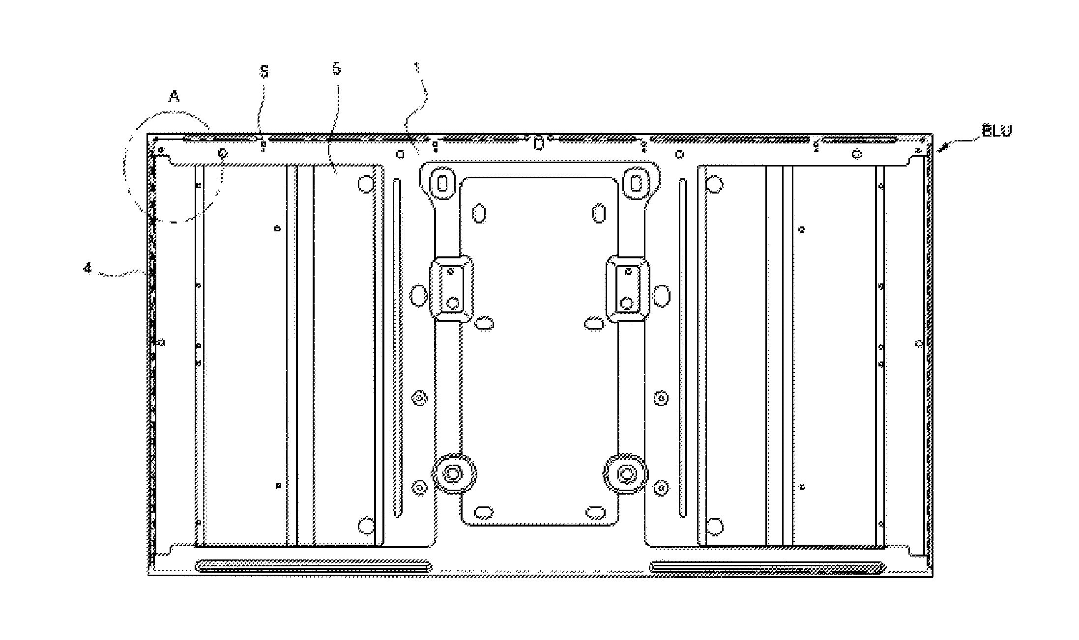
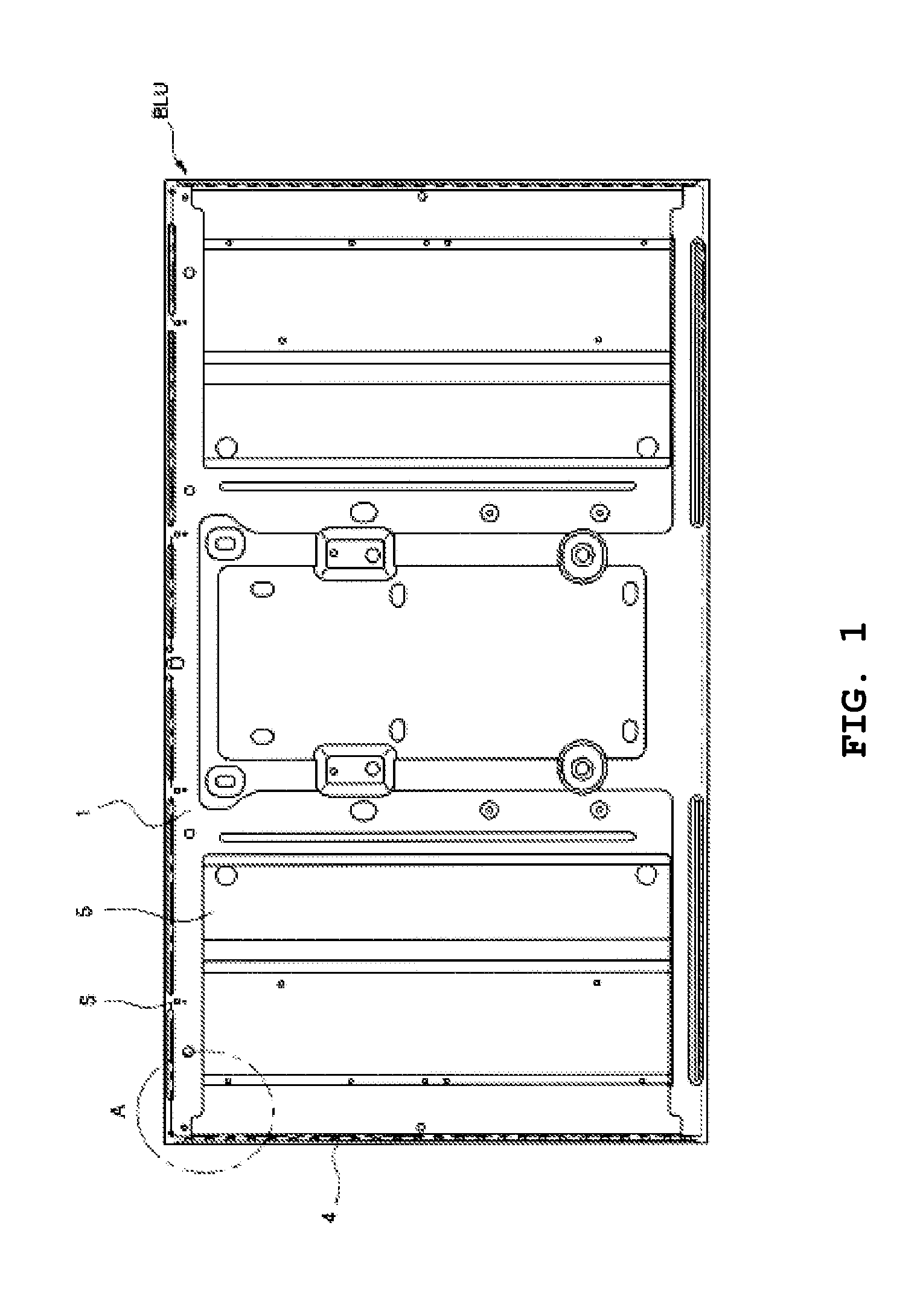
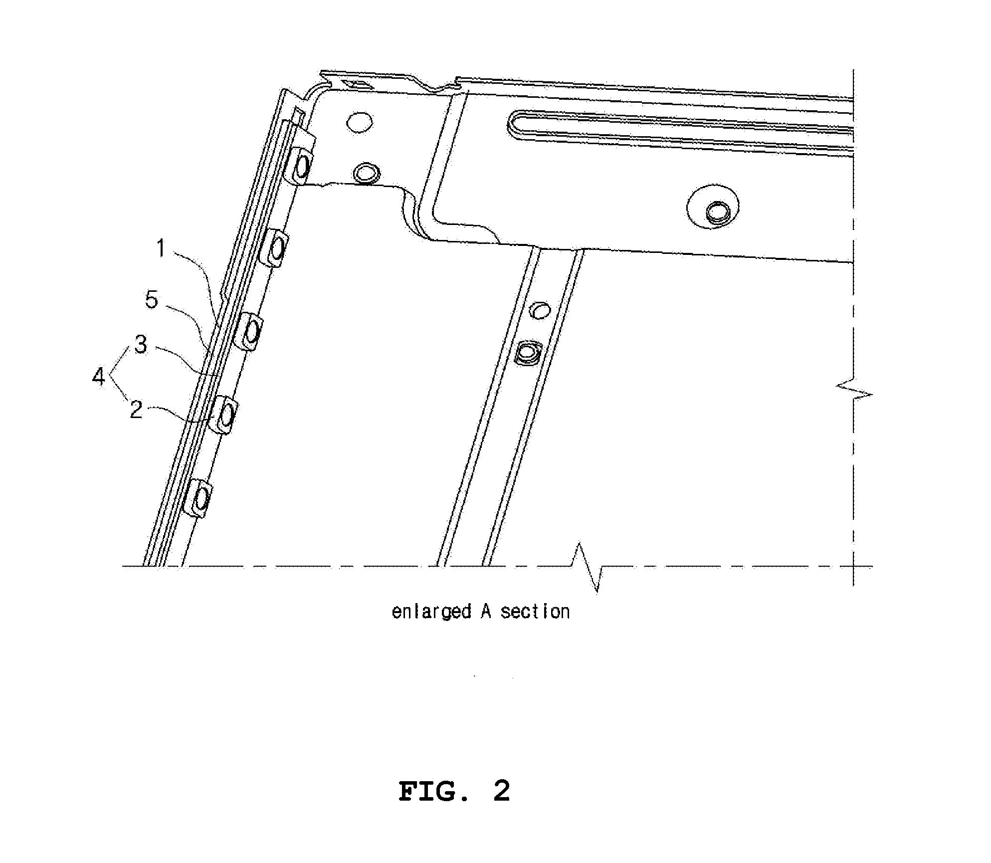
[0037]FIG. 4 is a front elevation view of a second embodiment of the present invention, and FIG. 5 is an enlarged perspective view of the second embodiment of the present invention.

[0038]Referring to the figures, a light source device according to the second embodiment proposes a construction which can realize heat dissipation ability that more rapidly dissipates heat generated by the LEDs 31 than the first embodiment.

[0039]For this, at least one side (both sides in the figures) of the rear cover 10 is open, and the heat dissipation cover 20 is coupled to the open portion of the rear cover 10. Here, the description that the rear cover 10 is open indicates that the wall surface of one or both sides of the rear cover 10 is removed and opened when the light source is coupled to the edge of the backlight unit BLU.

[0040]Specifically, the heat dissipation cover 20 is coupled to the open portion of the rear cover 10, and is applied so as to form part of the case construction, specifically,...

third embodiment

[0050]FIG. 6 is an enlarged perspective view of a third embodiment of the present invention.

[0051]Referring to the figure, a light source device according to the third embodiment proposes a construction which is employed when the light source is disposed directly below the backlight unit BLU.

[0052]For this, the light source device is configured such that a plurality of patterned substrates 32, on each of which a plurality of LEDs 31 are mounted, are disposed on the front surface of the rear cover 10, and the patterned substrates 32 are respectively coupled to a plurality of heat dissipation covers 20, which are then coupled to the rear cover 10.

[0053]The rear cover 10 has heat dissipation windows 24 in the front surface thereof, at positions where the heat dissipation covers 20 are to be coupled to the rear cover 10. The heat dissipation windows 24 allow the inside of the rear cover 10 to communicate with the outside, such that the heat dissipation covers 20 are exposed to the outsi...


PUM


Abstract

A light source device of a backlight unit in which a circuit board on which light-emitting diodes (LEDs) are mounted is disposed inside a rear cover and a heat dissipating means for dissipating heat generated from the LEDs to an outside is disposed between the rear cover and the circuit board. The circuit board is implemented as a patterned substrate which includes a thin sheet and a conductive pattern formed on the thin sheet, the conductive pattern connecting the LEDs to a power source, thereby reducing a thickness through which the heat generated by the LEDs is to be conducted to the heat dissipating means. The heat generated from the LEDs can be more rapidly and efficiently dissipated. Due to the more simplified structure, the light source device can be decreased in weight and be rapidly assembled.

Description

TECHNICAL FIELD[0001]The present invention relates, in general, to a light source device of a backlight unit for a display.[0002]More particularly, the present invention relates to a light source device in which heat generated from light-emitting diodes (LEDs) of a backlight unit, which is intended to act as a backlight source in a liquid crystal display (LCD) or an LED display, can be more rapidly and efficiently dissipated. At the same time, the light source device has a more simplified structure so that the light source device can be decreased in weight and be rapidly assembled.BACKGROUND ART[0003]Illumination using light-emitting diodes (LEDs) involves, for example, lighting equipment and a backlight unit (BLU) for a liquid crystal display (LCD) or an LED display.[0004]A display to which the backlight unit is applied is implemented as an LCD, an LED TV, a computer monitor, or the like. In these displays, a display panel is commonly implemented as an LCD or LEDs in order to displ...

Claims


Application Information

Patent Timeline
Patent Type & Authority Applications(United States)
IPC IPC(8): F21V29/00F21V8/00
CPCG02B6/0085F21V29/22G02F1/1336G02F1/133603G02F1/133608G02F1/133615G02F2201/46G02F1/133325G02F1/133628
Inventor HONG, SUNG CHUN
Owner FINE DNC
Why Eureka
Try Eureka