Ac/dc converter with passive power factor correction circuit and method of correcting power factor

a technology of power factor correction and ac/dc converter, which is applied in the direction of electric variable regulation, process and machine control, instruments, etc., can solve the problems of increased cost due to additional active switches, low power, waste of energy, etc., and achieve the effect of increasing the power factor and prolonging the life of the ac/dc converter

Inactive Publication Date: 2014-06-05
HEP TECH
View PDF7 Cites 5 Cited by
  • Summary
  • Abstract
  • Description
  • Claims
  • Application Information

AI Technical Summary

Benefits of technology

[0007]In view of the above, the primary objective of the present invention is to provide an AC / DC converter and a method of correcting a power factor, which effectively increases a power factor of the AC / DC converter, and has no need to adopt an electrolytic capacitor, thus prolongs life of the AC / DC converter.
[0016]With such design, it may prolong the conduction time of diodes in the rectifier circuit to control the input current of the AC power supply, which could increase the power factor effectively.

Problems solved by technology

Low power factor not only wastes energy, but also poses unnecessary burdens for the power supply systems of the power company.
However, the active power factor correction circuit has several drawbacks too, such as higher cost due to additional active switches, high electromagnetic noises, and low durability.
Because the inductor L has to be made from a bulk of silicon steel plate, its size increases along with the decreasing of output power and rated input voltage, and the power factor could merely achieve around 75%, which is insufficient to meet the demands nowadays.
Besides, in order to reduce the ripple of the output voltage of the loading R, the aforementioned output capacitor C has to adopt a high capacity electrolytic capacitor, but the electrolytic capacitor is easy to leak out the contained electrolyte due to being heated for a long period of time, which shortens life of circuit.

Method used


Image

  • Ac/dc converter with passive power factor correction circuit and method of correcting power factor
  • Ac/dc converter with passive power factor correction circuit and method of correcting power factor
  • Ac/dc converter with passive power factor correction circuit and method of correcting power factor

Examples


Embodiment Construction

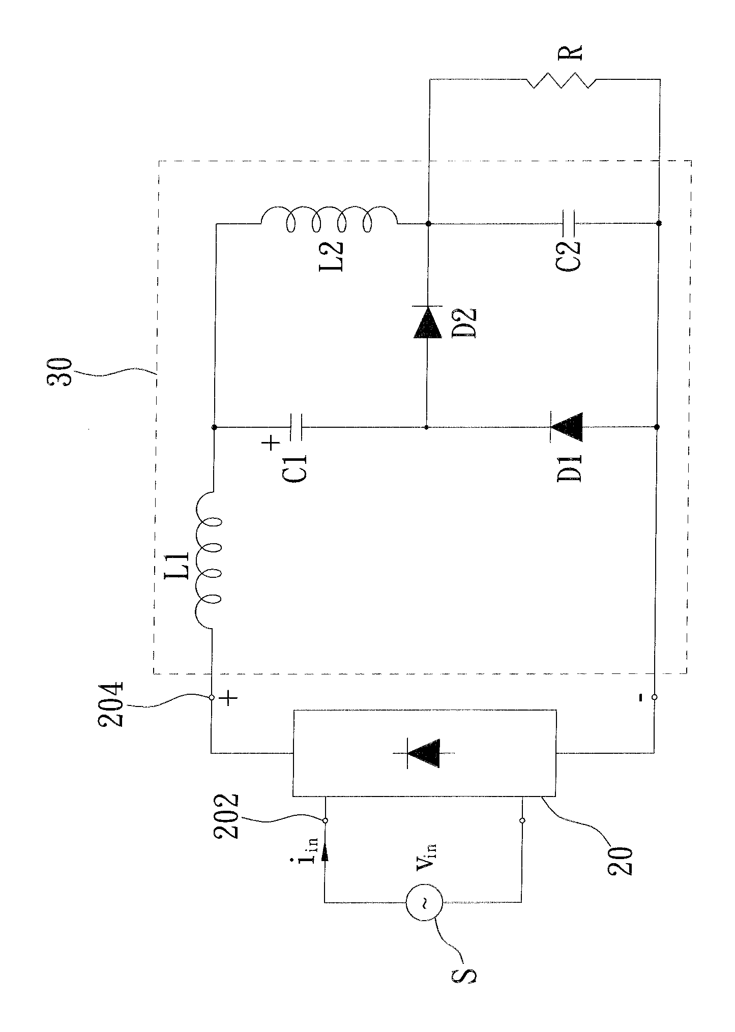
[0026]As shown in FIG. 3, an AC / DC converter of the preferred embodiment of the present invention includes a rectifier circuit 20 and a power factor correction circuit 30.

[0027]The rectifier circuit 20 is a full-wave bridge rectifier in the current embodiment, which has an input port 202 and an output port 204. The input port 202 is electrically connected to an AC power supply S, which provides an input voltage vin and an input current iin to the rectifier circuit 20. In the present embodiment, the AC power supply S is a city power line provided by a power station, but this is not the limitation of the present invention. In another embodiment, the input port 202 is connected to the city power line through a transformer which increases or decreases the voltage. Because of the rectifier circuit 20, the AC power supply S and the rectifier circuit 20 could be seen as a DC power supply as a whole, which sends a DC out via the output port 204 with twice the frequency.

[0028]The power facto...


PUM


Abstract

An AC / DC converter includes a rectifier circuit and a power factor correction circuit. An input port of the rectifier circuit receives an alternate current. The power factor correction circuit includes a first inductor, a second inductor, a first capacitor, a second capacitor, a first diode and a second diode. An end of the first inductor electrically connects to a positive pole of an output port of the rectifier circuit, and the other end electrically connects to a ground terminal of the output port through two parallel series routes which are bridged by the first diode. Wherein a series route contains the first capacitor and the second diode, and the other series route contains the second inductor and the second capacitor. The second capacitor is provided for parallel connecting with a loading. In this way, the input current could be controlled to increase the power factor effectively.

Description

[0001]The current application claims a foreign priority to the patent application of Taiwan No. 101145614 filed on Dec. 5, 2012.BACKGROUND OF THE INVENTION[0002]1. Technical Field[0003]The present invention relates generally to a power factor correction circuit, and more particularly to an AC / DC converter with passive power factor correction circuit and a method of correcting power factor.[0004]2. Description of Related Art[0005]Typically, an AC / DC converter is used to convert an alternate current (AC) into a direct current (DC). A conventional AC / DC converter is shown in FIG. 1, which includes a rectifier circuit 10 and an output capacitor C, wherein the rectifier circuit 10 converts an alternate current (AC) provided by an AC power supply S into a direct circuit (DC), and the output capacitor C bridges over the output of the rectifier circuit 10 and are in parallel with a loading R. While the AC / DC converter is working, the phases of the input voltage vin and the input current iin...

Claims


Application Information

Patent Timeline
Patent Type & Authority Applications(United States)
IPC IPC(8): H02M1/42
CPCH02M1/4266Y02B70/10Y02P80/10
Inventor PAN, CHING-TSAICHEN, PO-YENHUNG, TA-SHENG
Owner HEP TECH
Why Eureka
Try Eureka