Systems and methods of routing IP telephony data packet communciations

Inactive Publication Date: 2014-06-05
VONAGE BUSINESS
View PDF11 Cites 5 Cited by
  • Summary
  • Abstract
  • Description
  • Claims
  • Application Information

AI Technical Summary

Benefits of technology

The invention is about improving the quality of communication over IP telephony systems by controlling the path that data packets carrying the media of a telephony communication take as they travel between a calling and called telephony device. The invention allows for better control over the path that data packets traverse, which can improve call quality and reduce latency or delay in communication. This is important because the quality of a telephone call or other type of communication is highly dependent on how well the data packets carrying the media of the communication are being transmitted over the relevant data network.

Problems solved by technology

If data packets are being lost, call quality will deteriorate.
If transmitted data packets are being significantly delayed, call quality will deteriorate.
Another problem is jitter, where the latency or delay is variable in nature.
If jitter becomes a problem, call quality also will deteriorate.
Presently, IP telephony systems have only limited control over the path that data packets bearing the media of a telephony communication traverse as the data packets travel between a calling and called telephony device.
Unfortunately, this is not always a good assumption.
As a result, historical databases can only provide a prediction of the likely call quality that a media relay will provide based on how well the media relays performed in the past.
Unfortunately, there is no guarantee that a media relay that performed well in the past will perform well for a new call that is just being setup.
Moreover, even if the initial path that is established for a telephony communication provides good quality, there is always the possibility that network conditions may change while the telephony communication is ongoing, and that those changes may result in a deterioration of the quality provided by the initial path.

Method used


Image

  • Systems and methods of routing IP telephony data packet communciations
  • Systems and methods of routing IP telephony data packet communciations
  • Systems and methods of routing IP telephony data packet communciations

Examples


Embodiment Construction

[0034]The following detailed description of preferred embodiments refers to the accompanying drawings, which illustrate specific embodiments of the invention. Other embodiments having different structures and operations do not depart from the scope of the present invention.

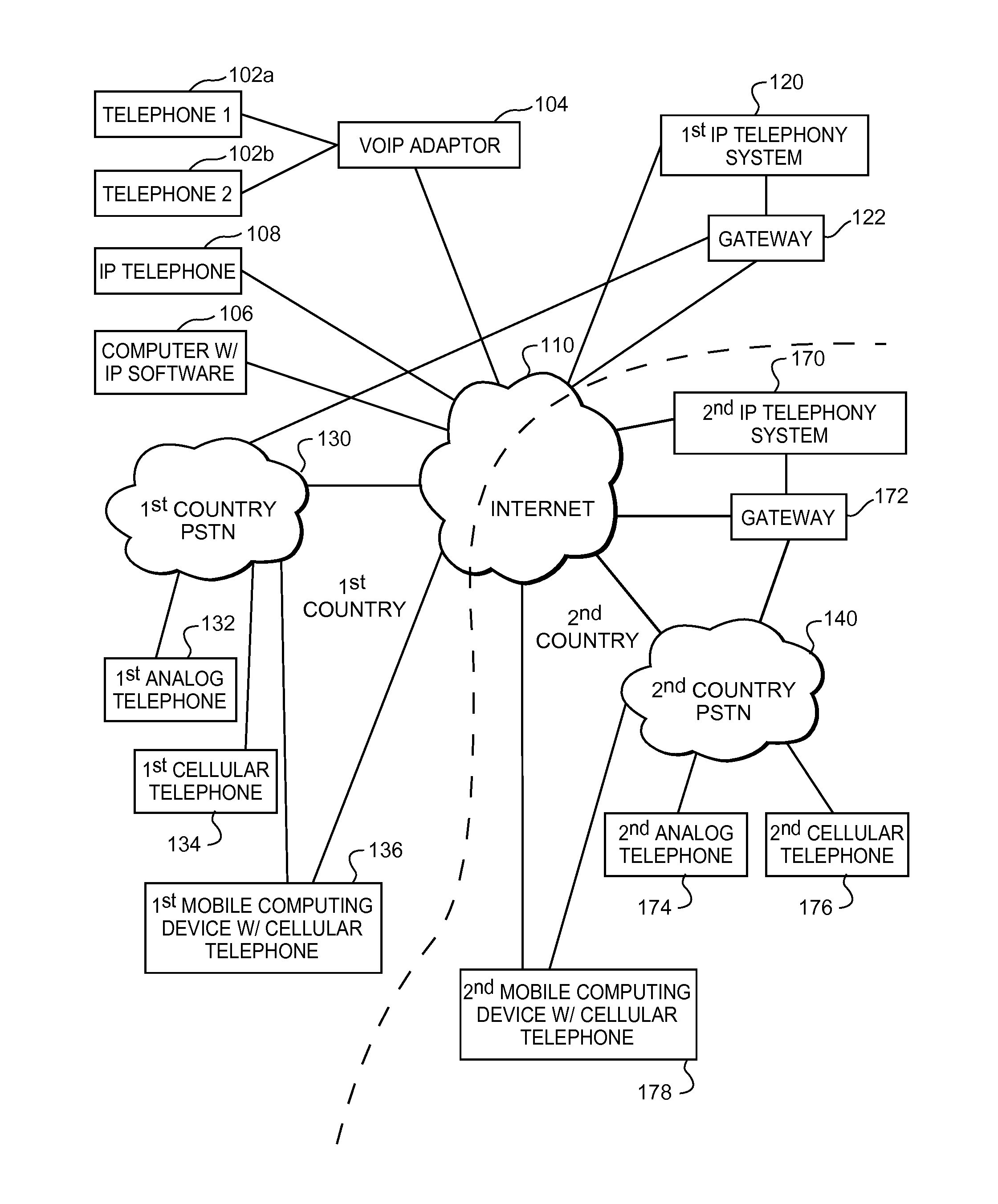
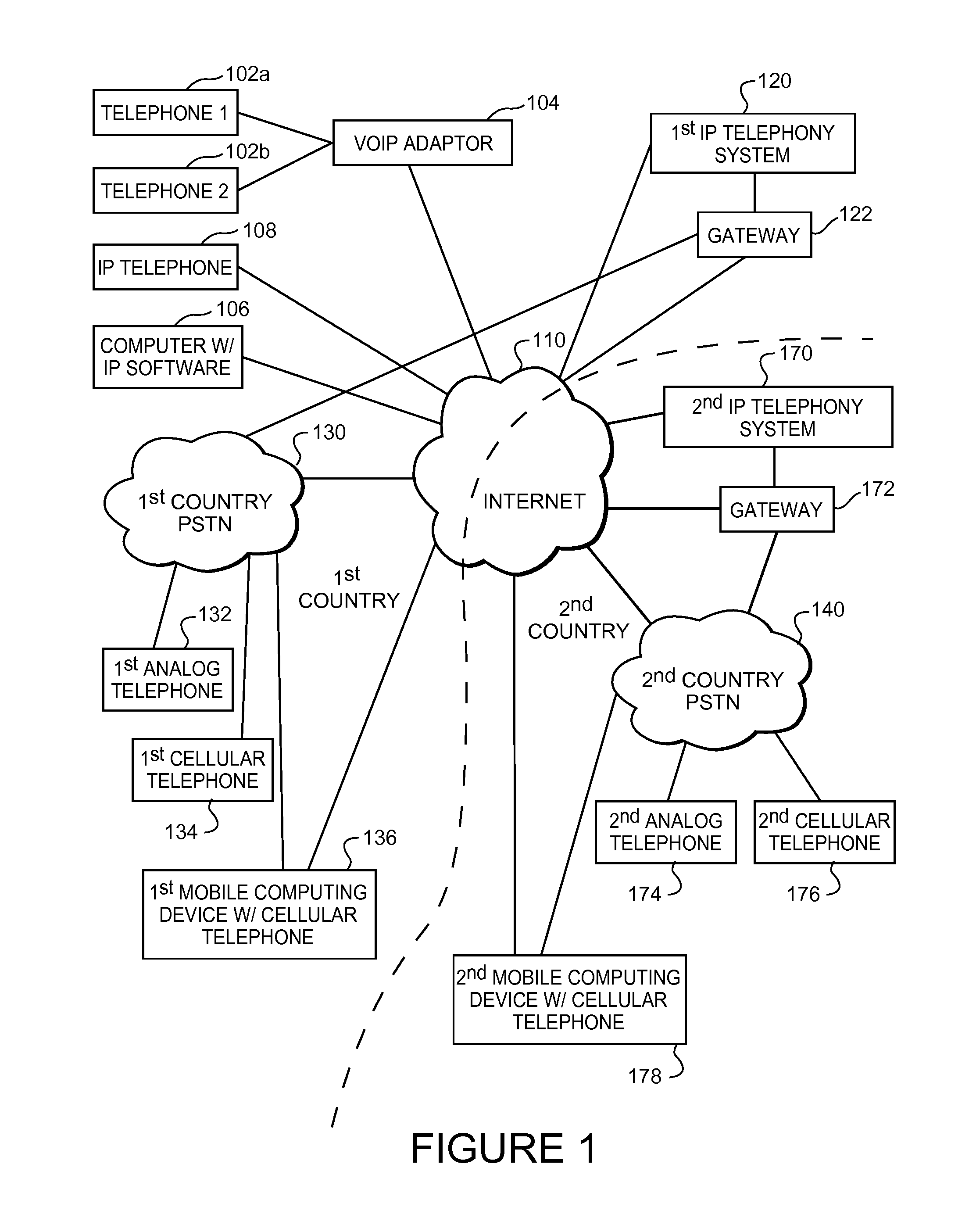
[0035]In the following description, the terms VOIP system, VOIP telephony system, IP system and IP telephony system are all intended to refer to a system that connects callers and that delivers data, text or video communications using Internet protocol data communications.

[0036]As illustrated in FIG. 1, a communications environment is provided to facilitate IP based communications. A first IP telephony system 120 enables connection of telephone calls between its own customers and other parties via data communications that pass over a data network. The data network is commonly the Internet 110, however, private data networks may form all or a portion of the data communication path. The IP telephony system 120 is co...


PUM


Abstract

Systems and methods performed by a telephony device allow the telephony device to test the quality of multiple potential paths which can be used to conduct a telephony communication. By testing the conditions that presently exist, the telephony device can choose the path that is presently offering the best quality. A telephony communication may be setup over an initial path, and then subsequent testing may determine that it is best to switch to an alternate path offering better call quality. The initial path used for the telephony communication may be the one that offers the fastest initial connection. When multiple potential paths exist, the telephony communication may be conducted over a first path while keep alive messages are communicated over a second path so that the telephony communication can be quickly switched to the second path.

Description

BACKGROUND OF THE INVENTION[0001]The invention is related to Internet Protocol (IP) telephony systems. More specifically, the invention is related to systems and methods for routing the data packets that carry communications enabled by an IP telephony system, such as telephone calls and text or video messages.[0002]Existing IP telephony systems allow users to place and receive telephone calls or to send and / or receive other types of communications, such as text messages, SMS messages, MMS messages and the like. The communications are transmitted, at least in part, by data packets that traverse a private and / or public data network.[0003]For example, a calling party can place a telephone call to a called party using an IP telephony device that is coupled to a private or public data network. When the user requests that the call be placed, an IP telephony system receives the request and sets up the call between the calling party's telephony device and the called party's telephony device...

Claims


Application Information

Patent Timeline
IPC IPC(8): H04L12/66
CPCH04L12/66H04L12/6418
Inventor BUCKO, ANDREWSTERMAN, BARUCH
Owner VONAGE BUSINESS
Why Eureka
Try Eureka