Developer supply container and developer supplying system

a technology of developer supply and supply container, which is applied in the direction of instruments, electrographic process equipment, optics, etc., can solve the problems of increasing cost and complicated structure of image forming equipment side, and achieve the effect of simplifying the mechanism of displacing the developer receiving portion to connect with the developer supply container

Active Publication Date: 2014-06-05
CANON KK
View PDF4 Cites 81 Cited by
  • Summary
  • Abstract
  • Description
  • Claims
  • Application Information

AI Technical Summary

Benefits of technology

[0015]According to the present invention, a mechanism for displacing the developer receiving portion to connect with the developer supply container can be simplified.
[0016]In addi...

Problems solved by technology

However, the device of Japanese Laid-open Patent Application Hei 08-11069 necessitates the driving source and the drive transmission mechanism for moving...

Method used


Image

  • Developer supply container and developer supplying system
  • Developer supply container and developer supplying system
  • Developer supply container and developer supplying system

Examples


embodiment 1

[0121]First, basic structures of an image forming apparatus will be described, and then, a developer receiving apparatus and a developer supply container constituting a developer supplying system used in the image forming apparatus will be described.

(Image Forming Apparatus)

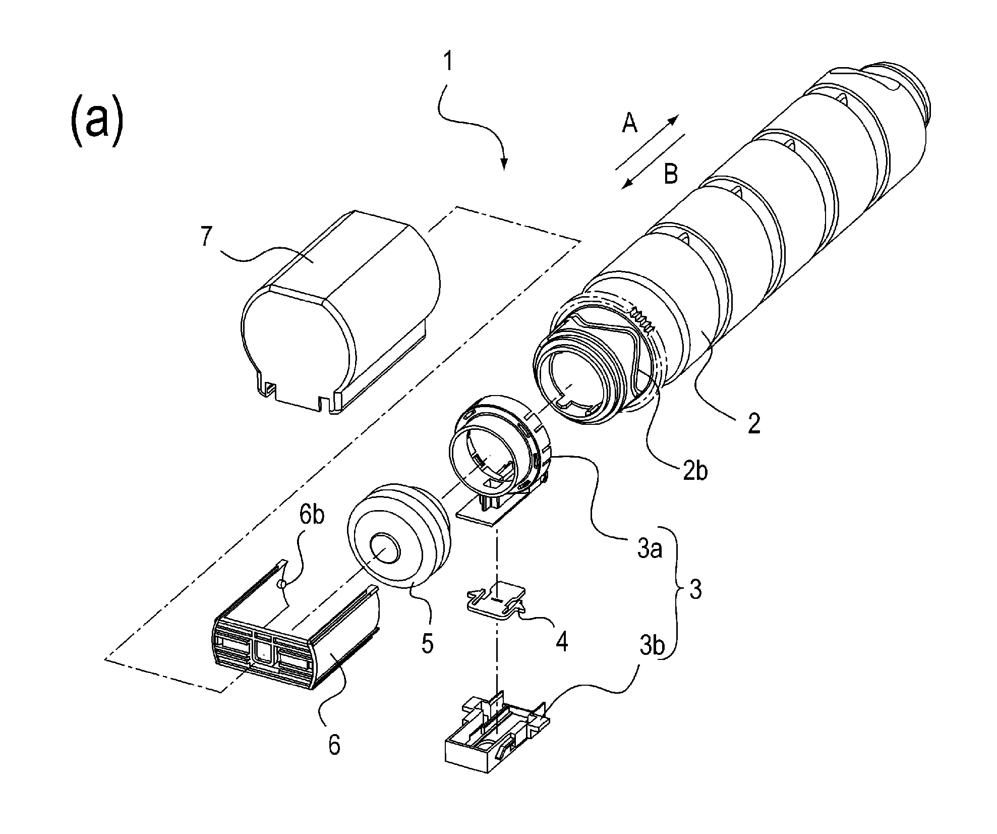
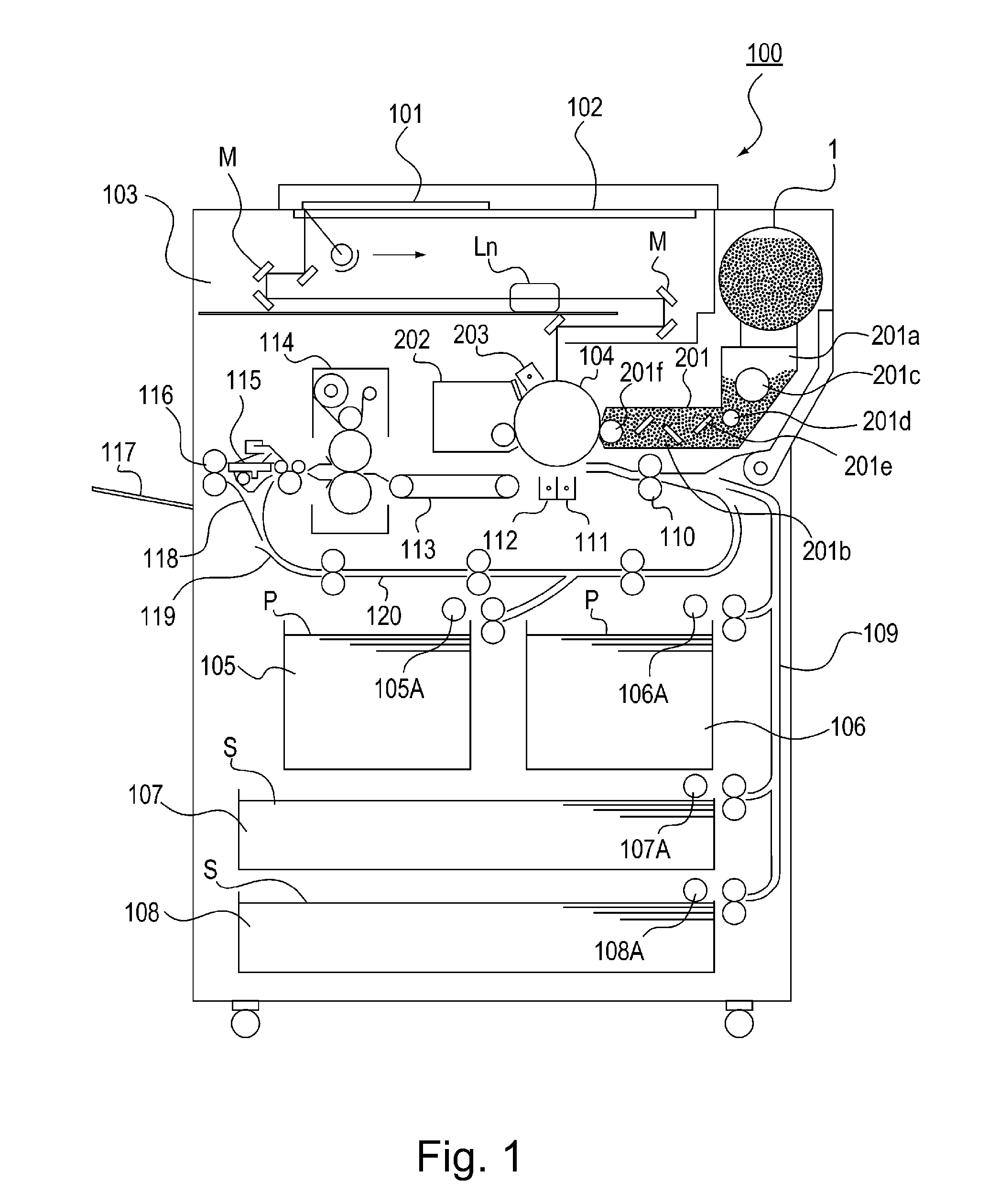
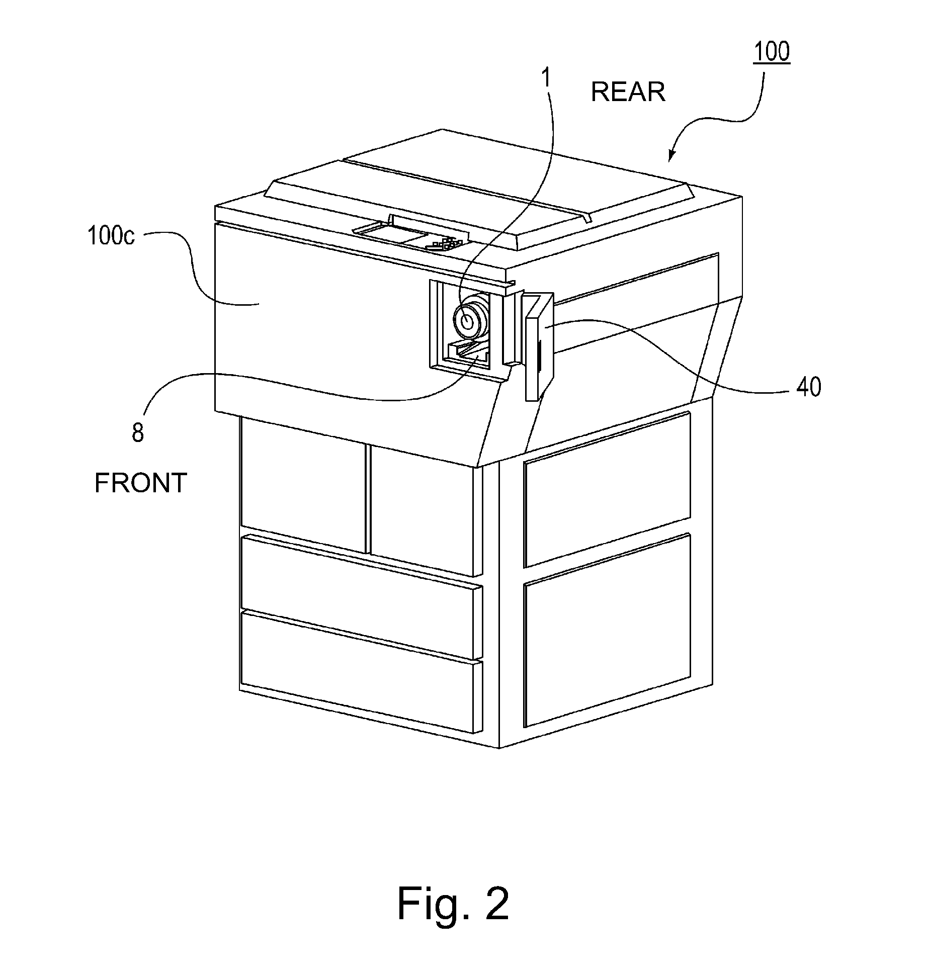
[0122]Referring to FIG. 1, the description will be made as to a structure of a copying machine (electrophotographic image forming apparatus) of an electrophotographic type as an example of an image forming apparatus comprising a developer receiving apparatus to which a developer supply container (so-called toner cartridge) is detachably (removably) mounted.

[0123]In the Figure, designated by 100 is a main assembly of the copying machine (main assembly of the image forming apparatus or main assembly of the apparatus). Designated by 101 is an original which is placed on an original supporting platen glass 102. A light image corresponding to image information of the original is imaged on an electrophotographic photos...

embodiment 2

[0210]Referring to FIG. 19FIG. 32, Embodiment 2 will be described. Embodiment 2 is partly different from Embodiment 1 in the configuration and structure developer receiving portion 11, the shutter 4, the lower flange portion 3b, and the mounting and demounting operations of the developer supply container 1 to the developer receiving apparatus 8 are partly different, correspondingly. Of other structures are substantially the same as Embodiment 1. In this example, the same reference numerals as in the foregoing embodiments are assigned to the elements having the corresponding functions in this embodiment, and the detailed description thereof is omitted.

(Developer Receiving Portion)

[0211]FIG. 19 shows the developer receiving portion 11 of Embodiment 2. Part (a) of FIG. 19 is a perspective view of the developer receiving portion 11, and part (b) of FIG. 19 is a sectional view of the developer receiving portion 11.

[0212]As shown in part (a) of FIG. 19, the developer receiving portion 11 ...

embodiment 3

[0260]Referring to FIGS. 33, 34, a structure of the Embodiment 3 will be described Part (a) of FIG. 33 is a partial enlarged view around a first engaging portion 3b2 of a developer supply container 1, and part (b) of FIG. 33 is a partial enlarged view of a developer receiving apparatus 8. Part (a)-part (c) of FIG. 34 are schematic view illustrating the movement of a developer receiving portion 11 in a dismounting operation. The position of part (a) of FIG. 34 corresponding to the position of FIGS. 15, 30, the position of part (c) of FIG. 34 corresponds to the position of FIGS. 13 and 28, the position of part (b) of FIG. 34 is therebetween and corresponds to the position of FIGS. 14, 29.

[0261]As shown in part (a) of FIG. 33, in this example, the structure of the first engaging portion 3b2 is partly different from those of Embodiment 1 and Embodiment 2. The other structures are substantially similar to Embodiment 1 and / or Embodiment 2. In this example, the same reference numerals as i...


PUM


Abstract

An object of the present invention is to provide a developer supply container capable of simplifying a mechanism for displacing a developer receiving portion to connect it with a developer supply container.
A developer supply container 1 for supplying a developer through a developer receiving portion 11 displaceably provided in a developer receiving apparatus 8 to which said developer supply container 1 is detachably mountable, said developer supply container 1 includes a developer accommodating portion 2c for accommodating a developer; and an engaging portions 3b2, 3b4, engageable with said developer receiving portion 11, for displacing said developer receiving portion 11 toward said developer supply container 1 with a mounting operation of said developer supply container 1 to establish a connected state between said developer supply container 1 and said developer receiving portion 11.

Description

FIELD OF THE INVENTION[0001]The present invention relates to a developer supply container detachably mountable to a developer receiving apparatus.[0002]Such a developer supply container is usable with an image forming apparatus of an electrophotographic type such as a copying machine, a facsimile machine, a printer or a complex machine having a plurality of functions of them.BACKGROUND ART[0003]Conventionally, an image forming apparatus of an electrophotographic type such as an electrophotographic copying machine uses a developer (toner) of fine particles. In such an image forming apparatus, the developer is supplied from the developer supply container with the consumption thereof by the image forming operation.[0004]Since the developer is very fine powder, it may scatter in the mounting and demounting of the developer supply container relative to the image forming apparatus. Under the circumstances, various connecting types between the developer supply container and the image formi...

Claims


Application Information

Patent Timeline
IPC IPC(8): G03G21/16
CPCG03G15/0879G03G21/1676G03G15/0886G03G15/00G03G15/08G03G15/0872G03G2215/0668
Inventor JIMBA, MANABUOKINO, AYATOMOMURAKAMI, KATSUYANAGASHIMA, TOSHIAKITAZAWA, FUMIO
Owner CANON KK
Why Eureka
Try Eureka