
Retrofit Catch Basin for use in Storm Water Management Practice

a catch basin and catch basin technology, applied in the field of stormwater management, can solve the problems of high construction cost of such overflow devices, inability to optimize stormwater collection, and inability to design, so as to achieve the effect of avoiding the cost of dedicated additional overflow structures, reducing construction costs, and reducing construction costs

Active Publication Date: 2014-06-05
THOMAS KYLE E
View PDF8 Cites 8 Cited by
  • Summary
  • Abstract
  • Description
  • Claims
  • Application Information

AI Technical Summary

Benefits of technology

The current invention is a way to retrofit existing catch basins and grates for better efficiency and cost savings. It uses a rack and covered grate assembly that diverts runoff to a common curb inlet structure while still allowing the existing catch basin to function as an overflow device. The new system also screens debris from the catch basin as effectively as the original. The benefit of this invention is that it avoids the cost of a dedicated additional overflow structure and increases the efficiency of collecting the curb inlet.

Problems solved by technology

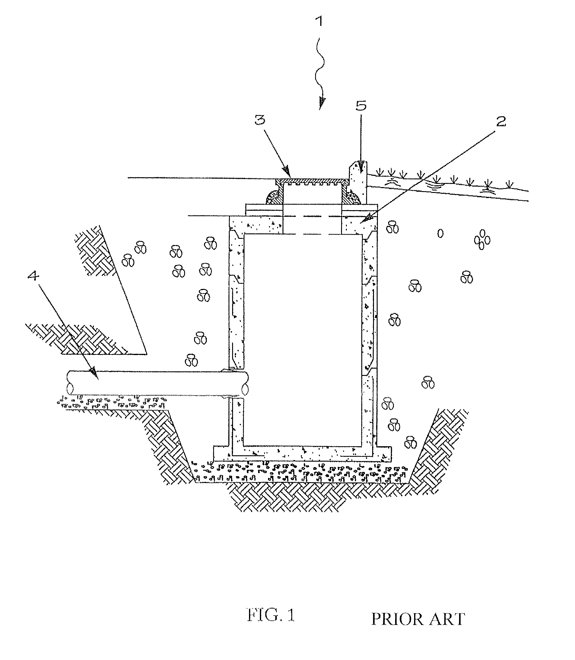
Construction of such overflow devices is typically a costly, invasive endeavor involving setting and plumbing of pre-cast or other manufactured overflow catch basin, plumbed into existing sewer systems located in the public street or right-of-way as discussed below.
This configuration does not, however, optimize stormwater collection as water that routs directly to the plane of the catch basin from the street 14 (i.e. not along the curbline) will continue to enter the catch basin and thus the sewer during rain events.

Method used


Image

  • Retrofit Catch Basin for use in Storm Water Management Practice
  • Retrofit Catch Basin for use in Storm Water Management Practice
  • Retrofit Catch Basin for use in Storm Water Management Practice

Examples


Embodiment Construction

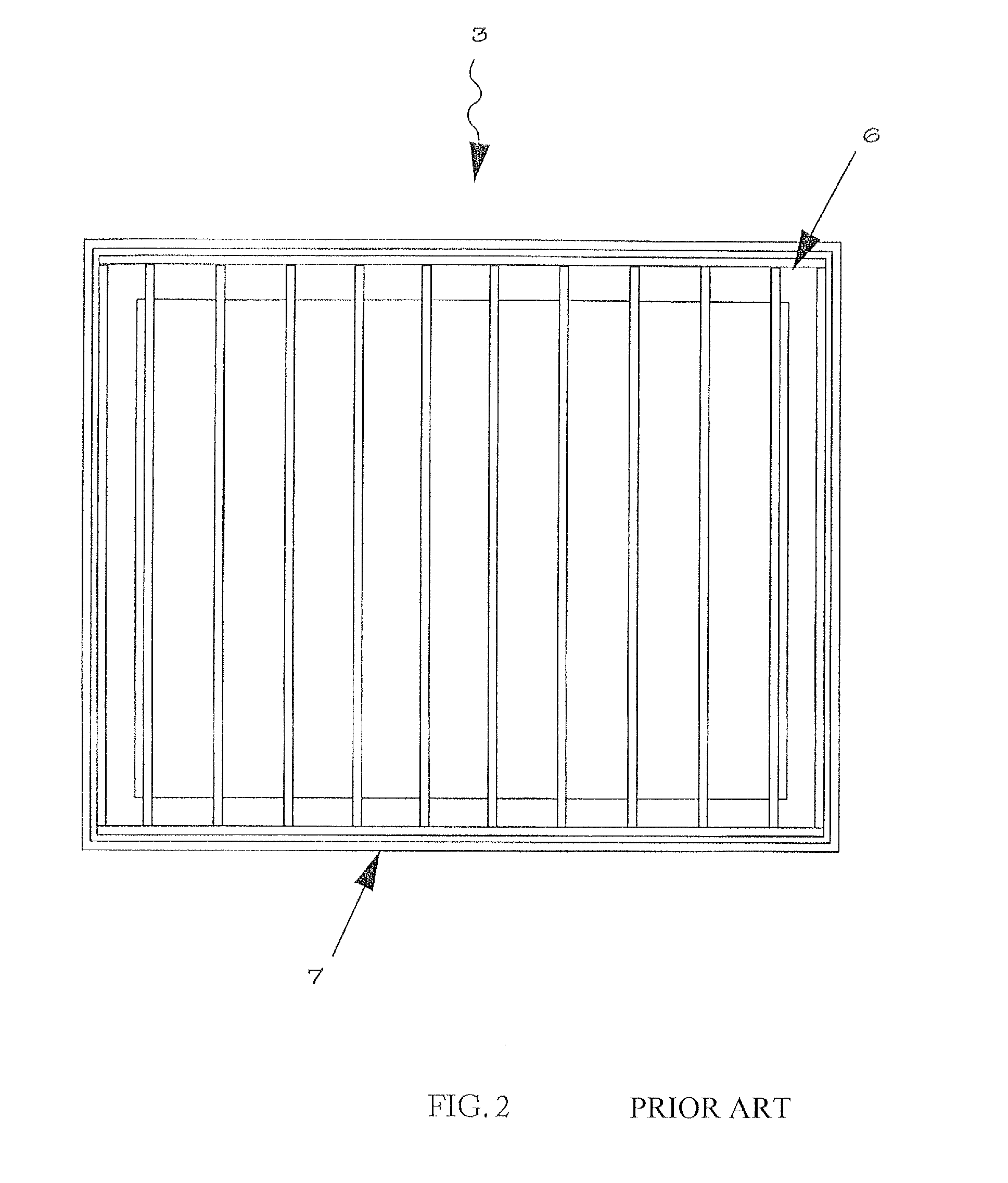
[0022]FIG. 8 shows the exemplary embodiment of the claimed invention. The exemplary diversion and overflow assembly generally consists of a grate 19 and cover plate 20 set in a frame 21. The grate and frame portion of the assembly is represented In FIG. 2 and is typical of a stormwater collection and trash screen device as is readily understood by those skilled in the art.

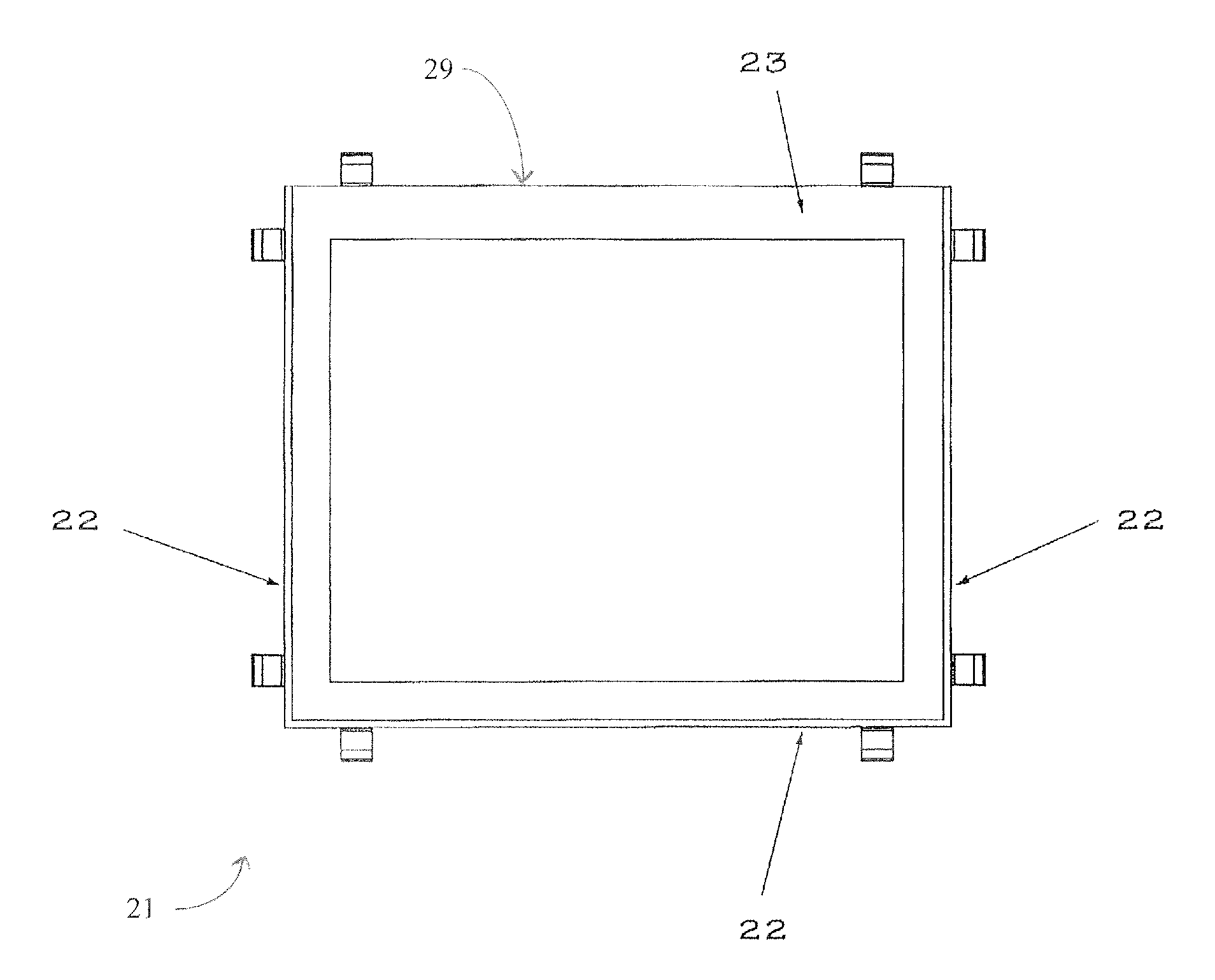
[0023]FIG. 9 depicts the frame portion of the claimed invention in plain view. On three sides, the frame is similar to the prior art catch basin frame by the presence of the angle material forming much of the strength of the assembly. The invention is distinguished, in part, from the conventional frame by the absence of the vertical from the angle forming the curbside edge 29 of the frame assembly 30. This portion of the frame consists of the horizontal member 23 only. The absence of the vertical portion of the curbside angle will allow the claimed invention to serve its overflow function by allowing flow to pass f...


PUM


Abstract

A catch basin retrofit that allows stormwater to be diverted from an existing storm sewer to an alternative stormwater management practice (SMP), while maintaining functionality of the catch basin as an overflow device for the alternative SMP.

Description

FIELD OF THE INVENTION[0001]The present invention relates to the field of stormwater management. More particularly it is an adaptation to existing conventional stormwater infrastructure to retrofit for an alternative SMP. It is particularly applicable where more modern “green infrastructure” technologies are being incorporated into existing urban drainage systems.BACKGROUND OF THE INVENTION[0002]Urban stormwater management has historically involved collection of rainwater and conveyance via piping to either directly to receiving waters or through via wastewater treatment plants (WWTPs). In dozens of cities in the United States such conveyance has occurred through combined sewer systems (Ms), which convey both stormwater and sewerage to WWTPs. Such CSSs are typically equipped with overflow devices that allow discharge directly to receiving waters from the sewer system when the sewer capacity is exceeded. Such combined sewer overflow (CSO) events contain not only stormwater but also u...

Claims


Application Information

Patent Timeline
IPC IPC(8): E01C11/22
CPCE01C11/223E03F5/046E03F5/101E03F5/105Y02A10/30E03F1/005E03F3/043E03F5/042E03F5/06E03F5/125
Inventor THOMAS, KYLE
Owner THOMAS KYLE E
Learn More