
Chain guide and chain transmission device

a transmission device and chain technology, applied in the direction of gearing, shaft and bearing, rotary machine parts, etc., can solve the problem that the proportion of radial loads applied tends to become worn locally, and achieve the effect of suppressing local wear on the roller shaft, improving wear resistance, and reducing the amount of radial loads

Inactive Publication Date: 2014-06-05
NTN CORP
View PDF11 Cites 4 Cited by
  • Summary
  • Abstract
  • Description
  • Claims
  • Application Information

AI Technical Summary

Benefits of technology

The invention allows for the rollers, which guide the timing chain and bearings, to move relative to the timing chain and rollers. This is achieved by supporting the rollers to move in the axial direction by roller shafts. As a result, the contact points between the timing chain and rollers, as well as between the rollers and roller shafts, can move in the axial direction, reducing wear and improving resistance to wear and tear.

Problems solved by technology

As a result, the portions where radial loads are applied tend to become worn locally.

Method used


Image

  • Chain guide and chain transmission device
  • Chain guide and chain transmission device
  • Chain guide and chain transmission device

Examples


Embodiment Construction

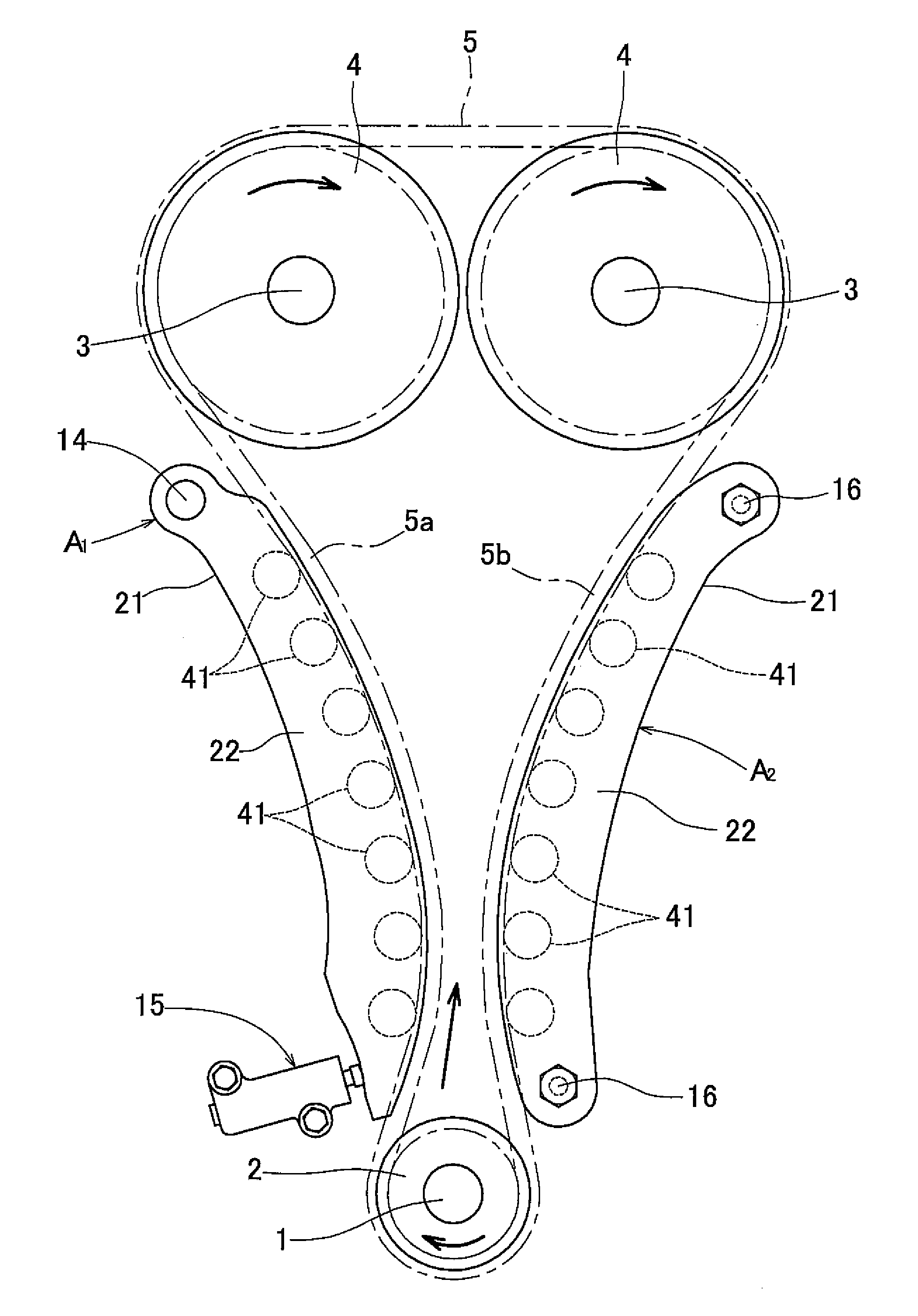
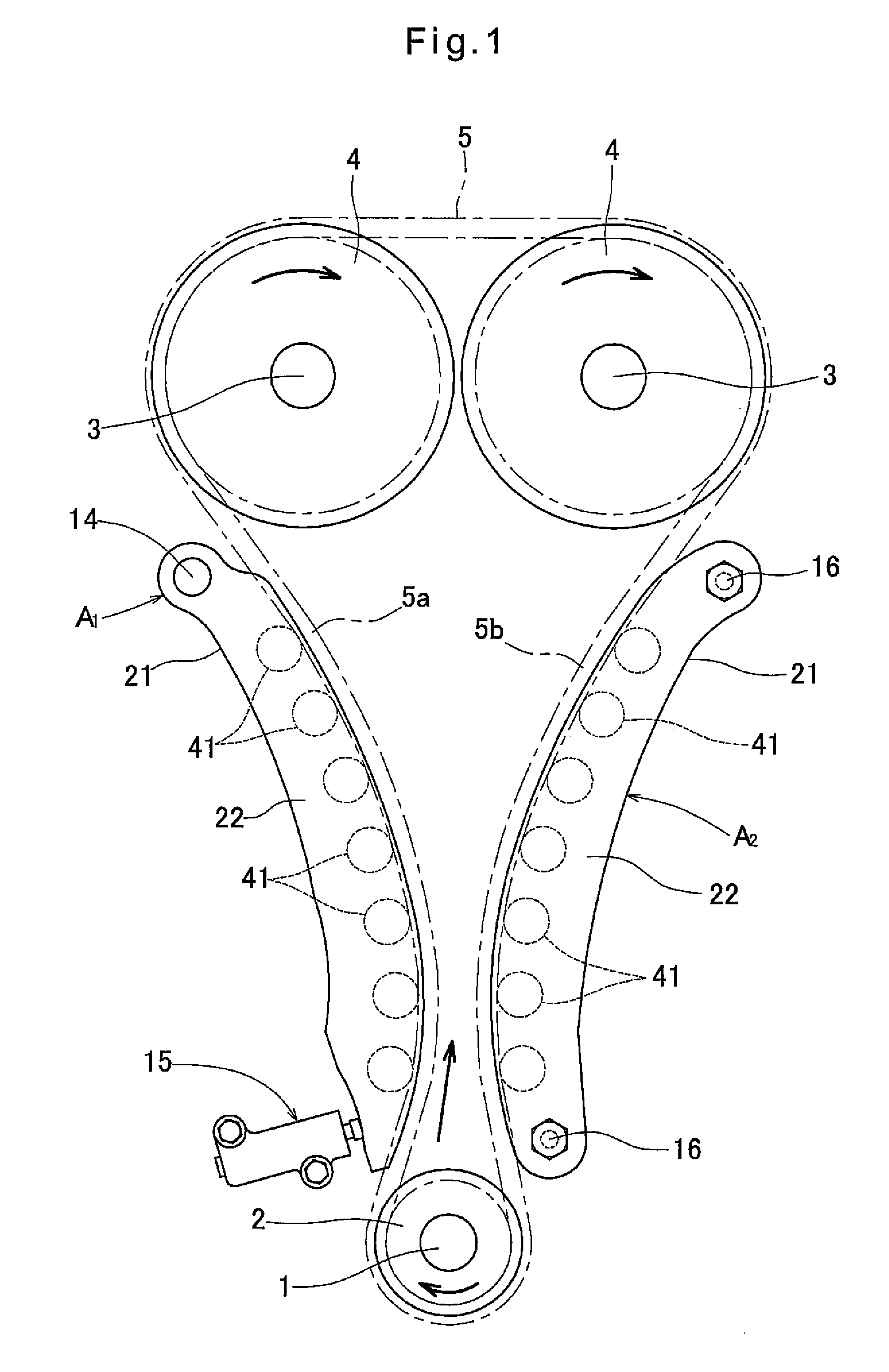
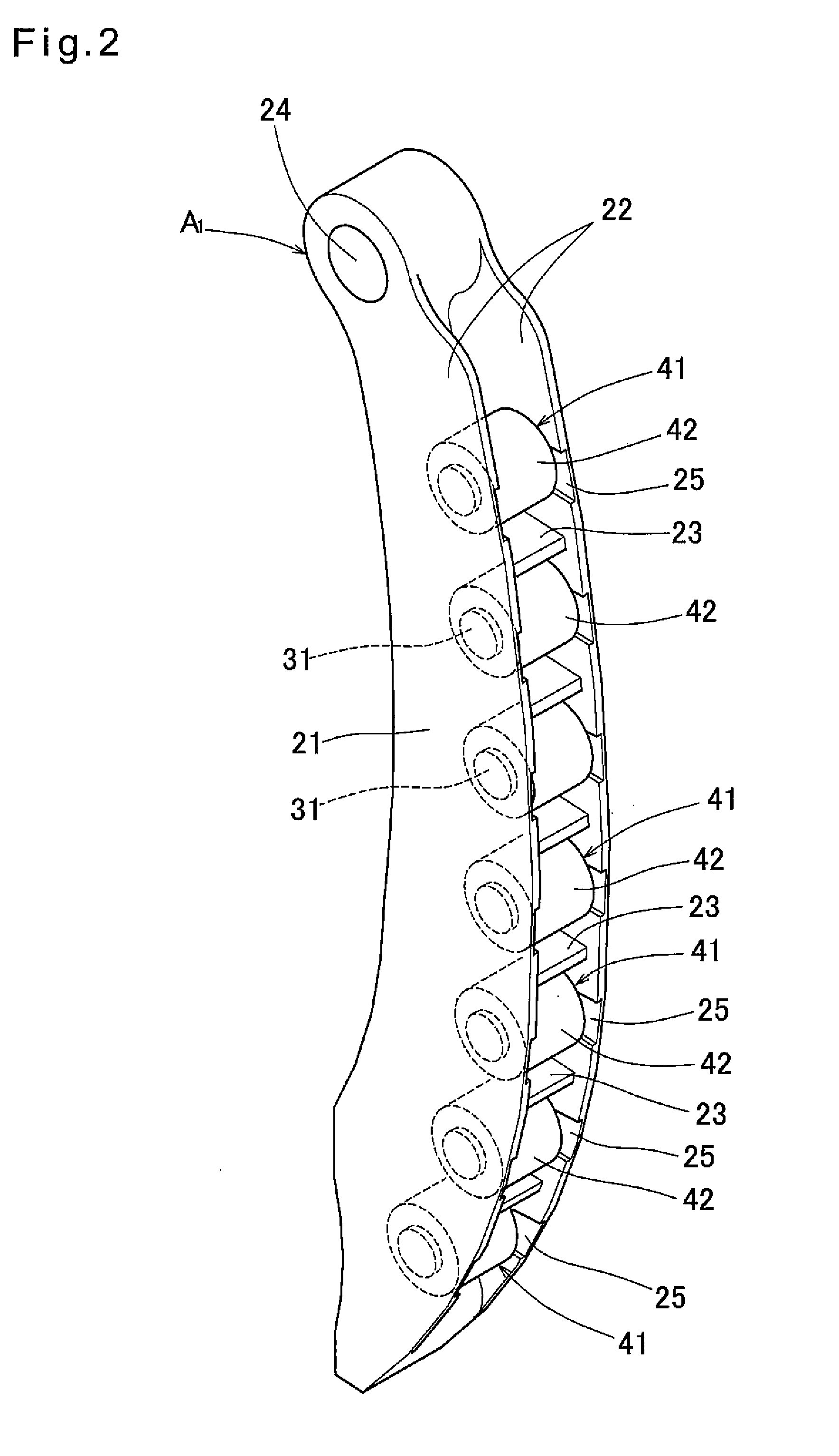
[0029]The embodiment of the present invention is now described with reference to the drawings. FIG. 1 shows a chain transmission device for driving camshafts, in which a timing chain 5 is looped over a driving sprocket 2 mounted to an end of a crankshaft 1 and driven sprockets 4 mounted to respective ends of two camshafts 3.

[0030]The timing chain 5 may be a roller chain or a silent chain.

[0031]The crankshaft 1 is rotated in the direction shown by the corresponding arrow of FIG. 1. By the rotation of the crankshaft 1, the timing chain 5 moves in the direction shown by the corresponding arrow of FIG. 1. As a result, the portion of the chain 5 extending from the driving sprocket 2 to the driven sprocket 4 on the left-hand side of FIG. 1 becomes slack (this side of the chain is thus referred to as the “slack side 5a”), and the portion of the chain extending from the other driven sprocket 4 to the driving sprocket 2 becomes tight (“tight side 5b”). A chain guide A1 is provided on one sid...


PUM


Abstract

A chain guide includes a plurality of roller shafts provided on one side of a timing chain for torque transmission and spaced from each other in the longitudinal direction of a guide base facing the timing chain. The respective roller shafts rotatably support chain guiding rollers in the form of needle roller bearings. The rollers are cylindrical members having the same diameter over the entire axial direction such that the rollers are movable in the axial direction relative to the timing chain. The rollers are supported so as to be movable in the axial direction. When the rollers and the timing chain move relative to each other in the axial direction and the rollers move relative to the roller shafts in the axial direction, contact portions between the rollers and the roller shafts are displaced in the axial direction, so that radial loads are not locally applied.

Description

TECHNICAL FIELD[0001]The present invention relates to a chain guide used for adjusting the tension of a chain or for guiding movements of the chain, and a chain transmission device including the chain guide.BACKGROUND ART[0002]In a chain transmission device for driving a camshaft in which a timing chain is looped over a driving sprocket attached to a crankshaft and a driven sprocket attached to the camshaft, a pivotable chain guide is provided on one side of the slack side of the timing chain, and adjustment force of a chain tensioner is applied to a remote end of the chain guide remote from the center of pivoting movement of the chain guide to tighten the timing chain, so that the chain is prevented from becoming slack and flapping.[0003]Another chain guide is fixed to the tight side of the timing chain, and movements of the timing chain are guided by the fixed chain guide.[0004]One known chain guide for adjusting the tension and for guiding the movement of the timing chain is conf...

Claims


Application Information

Patent Timeline
Patent Type & Authority Applications(United States)
IPC IPC(8): F16H7/20
CPCF16H7/20F16C13/006F16C33/588F16C2240/60F16C2361/63F16H7/1281F16H2007/0865F16H2007/0893
Inventor KATO, AKIOOISHI, SHINJI
Owner NTN CORP
Features
  • Generate Ideas
  • Intellectual Property
  • Life Sciences
  • Materials
  • Tech Scout
  • Unparalleled Data Quality
  • Higher Quality Content
  • 60% Fewer Hallucinations
Learn More