Pneumatic tire

Active Publication Date: 2013-03-21
TOYO TIRE & RUBBER CO LTD
View PDF1 Cites 12 Cited by
  • Summary
  • Abstract
  • Description
  • Claims
  • Application Information

AI Technical Summary

Benefits of technology

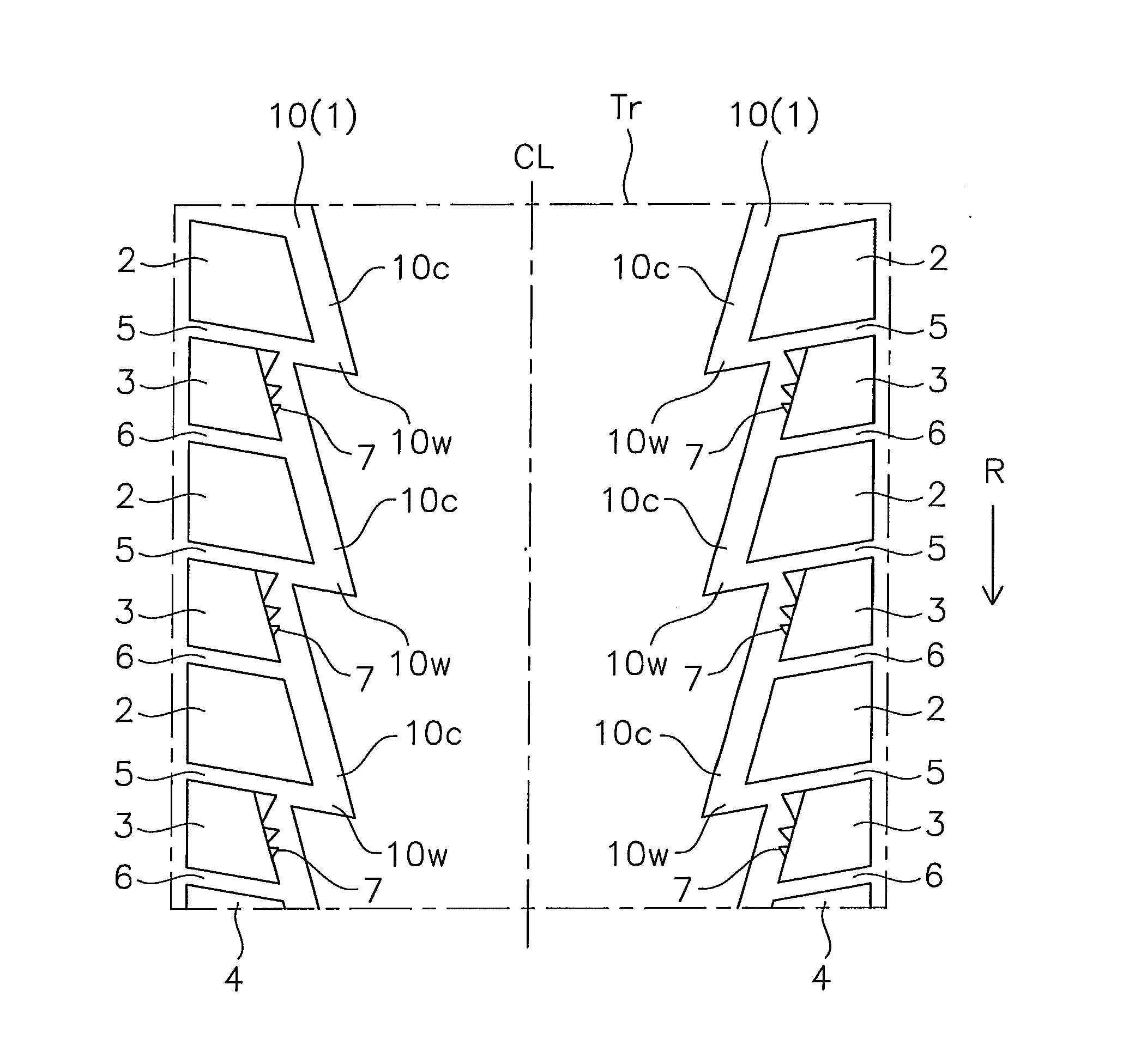
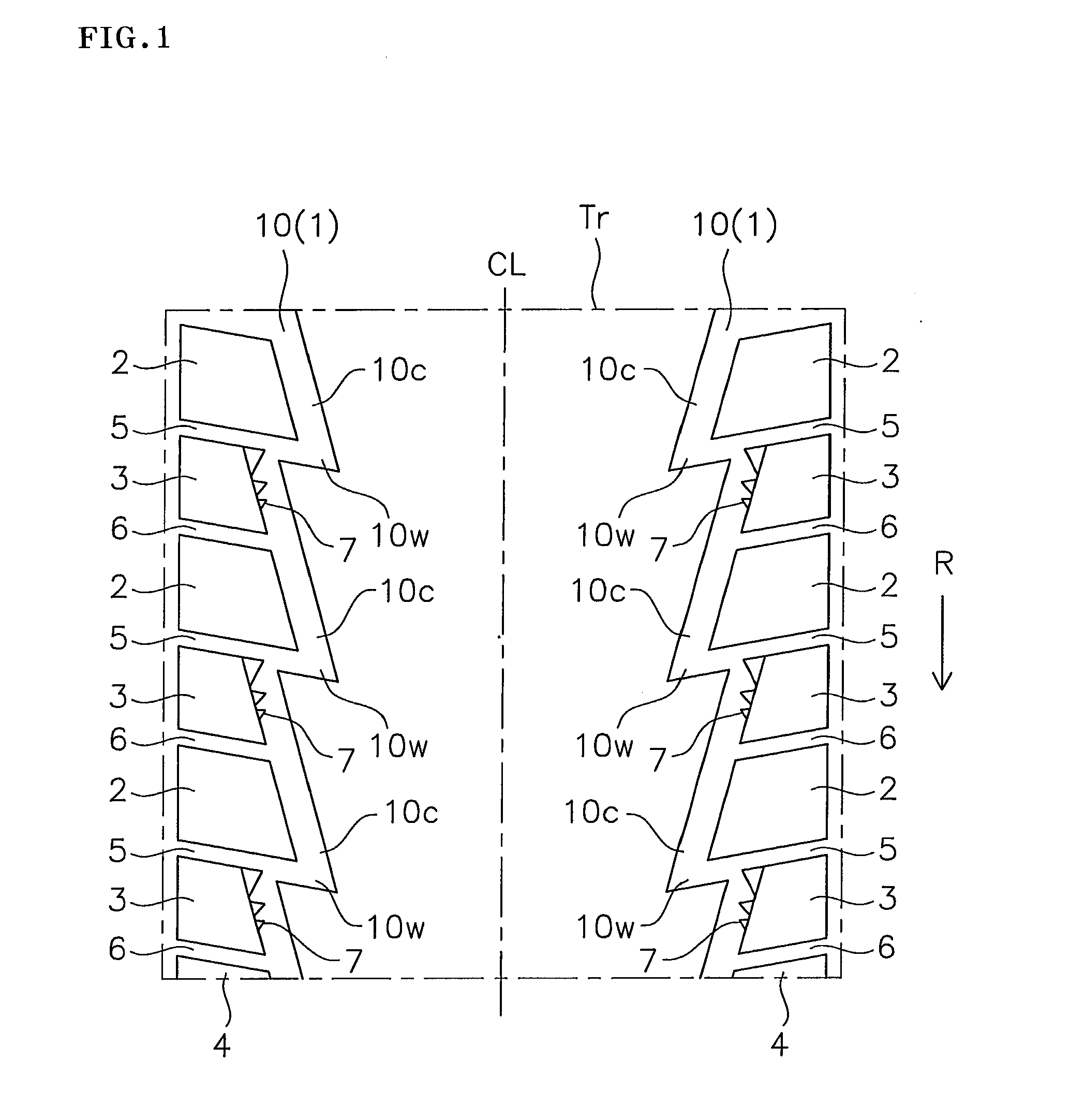
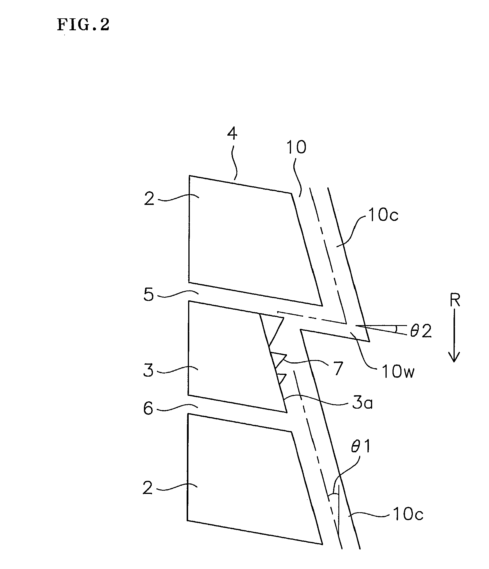
[0016]The pneumatic tire is provided in the tread surface with the shoulder main groove and the shoulder block row as mentioned above, and the heel and toe wear tends to be generated particularly in the second block in the block which constructs the shoulder block row. Accordingly, in the present invention, a plurality of projections which are elevated from the groove bottom of the shoulder main groove and protrude from the side wall of the second block are provided so as to be spaced at the distance in the tire circumferential direction, and a volume of the projections is made larger in the trailing side than in the leading side. In accordance with this, it is possible to suppress a change in the slip direction of the shoulder main groove side portion of the second block and make the slip amount small, thereby preventing the heel and toe wear.
[0017]Further, in the pneumatic tire, since a plurality of projections are provided so as to be spaced at the distance in the tire circumferential direction, it is possible to suppress the volumetric capacity reduction of the shoulder main groove due to the projections, thereby suppressing the deterioration of the drainage performance. Further, since the slip of the block is suppressed, and a rigidity of the block is enhanced by setting a plurality of projections, it is possible to improve a steering stability.
[0018]In the present invention, it is preferable that the number of the projections which are provided in the side wall of the second block is three or four, and the volume of the projection becomes larger toward the trailing side of the second block. In accordance with this, in the side wall of the second block, the relatively larger projection is provided in the trailing side, the relatively smaller projection is provided in the leading side, and the projection having the intermediate size is provided in the center. Therefore, it is possible to accurately achieve the effect of suppressing the change of the slip direction of the shoulder main groove side portion of the second block

Problems solved by technology

The pneumatic tire is provided in the tread surface with the shoulder main groove and the shoulder block row as mentioned above, an

Method used


Image

  • Pneumatic tire
  • Pneumatic tire
  • Pneumatic tire

Examples


Example

Example

[0061]An example which concretely shows the structure and effect of the present invention will be explained. A tire to be provided for evaluation is set such that a size is 225 / 40R18. The tire is assembled to a rim of 18×8JJ so as to be installed to a vehicle, a pneumatic pressure is 230 kPa, and a vertical load is 4903 N.

[0062](1) Heel and Toe Wear Resistance

[0063]After traveling for 12000 km, a worn state of a block (a second block) in which a heel and toe wear is regarded as problem was observed, and a form and an area of a region where the wear is significant was searched. The form was illustrated, and the area was expressed by a rate with respect to an area of a top surface of the block before being worn.

[0064](2) Drainage Performance (Hydroplaning Resistance Performance)

[0065]The tire was rolled on a wet road surface having a water depth 8 mm, and a speed at a time when a hydroplaning phenomenon is generated was measured. An evaluation is carried out by an index number ...

Example

[0068]In a comparative example 1, a projection is not provided in the block 3 as shown in FIG. 7. In a comparative example 2, a pair of projections 20 are provided in the block 3 and they are connected to a land portion 21 as shown in FIG. 8. In a comparative example 3, a projection 30 is provided in a whole surface of the side wall 3a of the block 3 as shown in FIG. 9. In a comparative example 4, only a projection 7a in a trailing side is provided in the block 3 as shown in FIG. 10. In working examples 1 and 2, triangular projections 7 are provided as shown in FIGS. 11 and 12, and in working examples 3 and 4, step-like projections 8 are provided as shown in FIGS. 13 and 14.

[0069]In FIGS. 7 to 14, the same reference numerals are attached to the same structure as the structure which is described in the embodiment mentioned above. Further, in the evaluation of the heel and toe wear resistance, a region in which the wear is significant is colored by black, and a direction and a magnitu...


PUM


Abstract

A shoulder main groove has a plurality of circumferential components inclined to an inside in a tire width direction toward a forward in a tire rotating direction. The circumferential components are communicated with each other via a lateral groove. A shoulder block row includes a first block positioned in a rear side in the tire rotating direction of the circumferential component, and a second block which has a smaller area of a top surface than the first block, and is adjacent to the first block with the lateral groove sandwiched therebetween. A plurality of projections elevating from a groove bottom and protruding out of a side wall of the second block are provided. A volume of the projection positioned in a trailing side of the second block is larger than a volume of the projection positioned in a leading side.

Description

BACKGROUND OF THE INVENTION[0001]1. Field of the Invention[0002]The present invention relates to a pneumatic tire in which a tread surface is provided with a plurality of main grooves which extend in a tire circumferential direction, and a shoulder block row which is arranged in an outer side in a tire width direction of a shoulder main groove positioned in an outermost side in the tire width direction in the main grooves.[0003]2. Description of the Related Art[0004]There has been known a structure in which an outer side in a tire width direction of a shoulder main groove is provided with a shoulder block row formed by arranging a plurality of blocks in a tire circumferential direction. Generally, an outer diameter is smaller in both end sides of a tread surface than in a center, and the block tends to generate a slip in the shoulder block row due to the diameter difference. Particularly, since a trailing side portion of the block elastically deforms largely in a tire circumferentia...

Claims


Application Information

Patent Timeline
IPC IPC(8): B60C11/01
CPCB60C11/01B60C2011/1338B60C11/1323B60C2011/0346B60C11/0302B60C11/0309
Inventor SUITA, HARUNOBU
Owner TOYO TIRE & RUBBER CO LTD
Why Eureka
Try Eureka