System for Protecting an Inner Wall of a Combustor

a technology of combustor and inner wall, which is applied in the direction of efficient propulsion technology, machines/engines, light and heating apparatus, etc., can solve the problems of unsatisfactory consumption/depletion, costly repairs and replacements

Inactive Publication Date: 2014-06-12
GENERAL ELECTRIC CO
View PDF3 Cites 6 Cited by
  • Summary
  • Abstract
  • Description
  • Claims
  • Application Information

AI Technical Summary

Problems solved by technology

Unfortunately, the hot combustion gases may oxidize the combustor causing undesirable consumption / depletion.
Over time excessive oxidization may result in costly repairs and replacement.

Method used


Image

  • System for Protecting an Inner Wall of a Combustor
  • System for Protecting an Inner Wall of a Combustor
  • System for Protecting an Inner Wall of a Combustor

Examples


Embodiment Construction

[0019]Certain embodiments commensurate in scope with the originally claimed invention are summarized below. These embodiments are not intended to limit the scope of the claimed invention, but rather these embodiments are intended only to provide a brief summary of possible forms of the invention. Indeed, the invention may encompass a variety of forms that may be similar to or different from the embodiments set forth below.

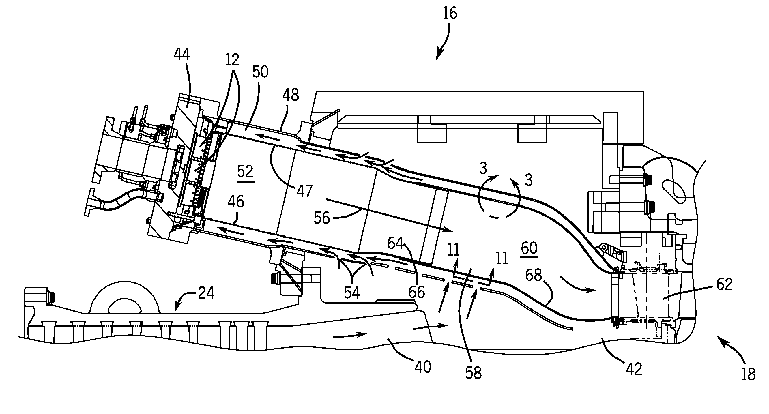
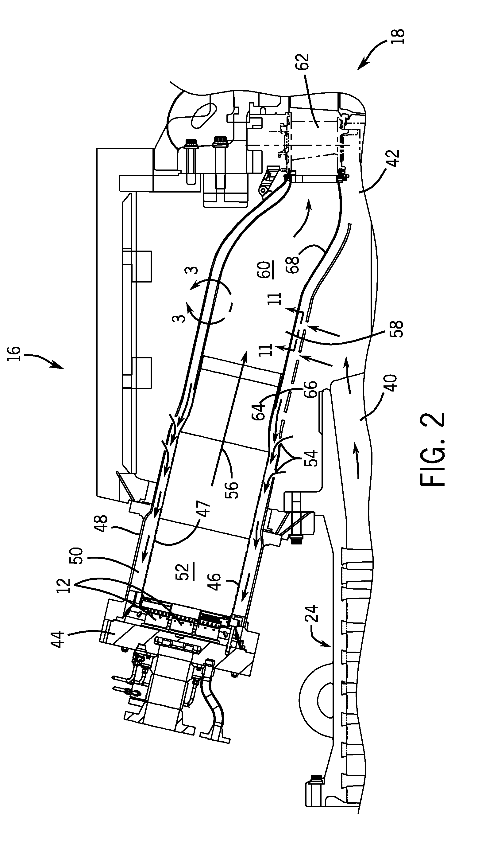
[0020]The disclosed embodiments are generally directed towards a system for protecting an inner wall of a combustor. More specifically, the disclosed embodiments are directed towards an oxidation initiated effusion cooling system, a thermal barrier coating spallation initiated effusion cooling system, or a combination thereof. These systems enable a cooling airflow or protective film to cover the inner wall of the combustor, thereby blocking the hot combustion gases from oxidizing (e.g., depleting, consuming, etc.) the combustor wall. For example, the oxidation ini...


PUM


Abstract

In a first embodiment a system, including a gas turbine combustor, including an inner wall disposed about a combustion chamber, and an outer wall disposed about the inner wall, wherein a coolant flow path extends between the inner and outer walls, wherein the inner wall comprises a material blocking a plurality of openings, and the plurality of openings are configured to open after the material is consumed or depleted to define a plurality of coolant passages through the inner wall.

Description

BACKGROUND[0001]The subject matter disclosed herein relates to gas turbine engines and, more specifically, to a system for protecting an inner wall of a combustor.[0002]Gas turbine engines may include a combustor having a liner, and a transition piece that connects the combustor to a turbine. As an air-fuel mixture combusts inside of the combustor, the hot combustion gases travel through the combustor and into the turbine, generating power. Unfortunately, the hot combustion gases may oxidize the combustor causing undesirable consumption / depletion. Over time excessive oxidization may result in costly repairs and replacement.BRIEF DESCRIPTION[0003]In a first embodiment a system, including a gas turbine combustor, including an inner wall disposed about a combustion chamber, and an outer wall disposed about the inner wall, wherein a coolant flow path extends between the inner and outer walls, wherein the inner wall comprises a material blocking a plurality of openings, and the plurality...

Claims


Application Information

Patent Timeline
Patent Type & Authority Applications(United States)
IPC IPC(8): F23R3/00
CPCF23R3/002F23R3/005F23R3/007F23R3/06F23R2900/00019F23R2900/03041F23R2900/03042Y02T50/60
Inventor KIDDER, KYLE LEEBROWN, JEROME D.
Owner GENERAL ELECTRIC CO
Why Eureka
Try Eureka