Downhole gas separator and method

a gas separator and downhole technology, applied in the direction of fluid removal, borehole/well accessories, construction, etc., can solve the problems of limited use, cost and complexity of these devices, and achieve the effect of reducing the cost and complexity

Active Publication Date: 2014-06-12
COBB DELWIN E +1
View PDF7 Cites 22 Cited by
  • Summary
  • Abstract
  • Description
  • Claims
  • Application Information

AI Technical Summary

Benefits of technology

[0007]In one embodiment, the downhole separator supported on a tubular in a borehole separates gas from well fluids which are pumped intermittently to the surface. The downhole separator includes an outer tubular housing having openings therein to receive well fluids from an annulus radially exterior of the outer tubular housing. An inner flow tube secured to the tubular and having an open lower end passes upward flow of well fluids after separation of the gas from the well fluids. A vortex flow separator radially between the inner flow tube and the outer tubular housing receives the well fluids from the tubular housing openings and imparts a helical flow to effect separation of the gas from the well fluids. The gas accumulates in a chamber below the vortex flow generator and between the outer tubular housing and the inner flow tube when well fluids are pumped to the surface. Gas from the gas chamber flows upward past the vortex flow separator and exits the openings in the outer tubular housing when the pump is not pumping well fluids to the surface, i.e., during the plunger return cycle.

Problems solved by technology

The size, cost and complexity of these devices have limited their use in the oil and gas recovery industry.

Method used


Image

  • Downhole gas separator and method
  • Downhole gas separator and method
  • Downhole gas separator and method

Examples


Embodiment Construction

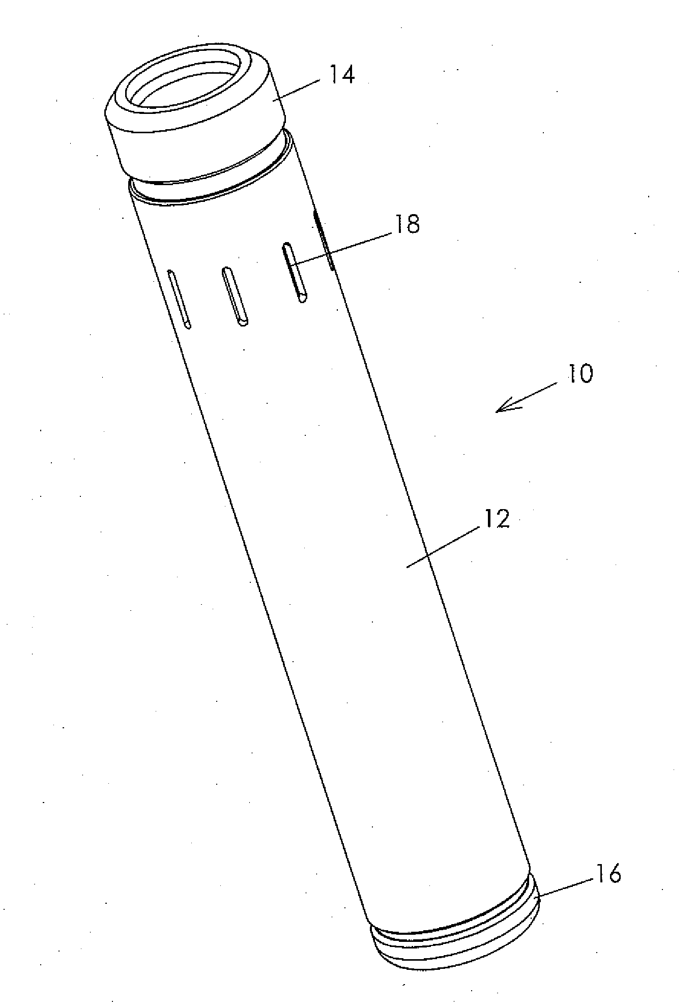
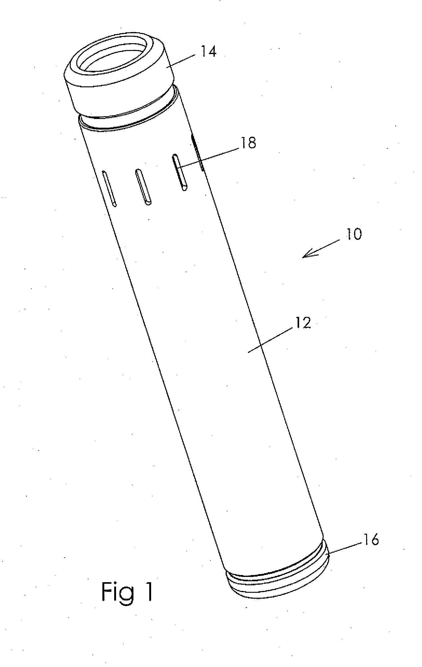
[0013]FIG. 1 illustrates one embodiment of a separator 10 including a tubular outer housing 12. Coupling 14 is provided for interconnection to a tubular (not shown) which runs the separator in a well, with the coupling 14 also threadably connected to the housing 12. The plug 16 at the lower end of housing 12 is provided for ensuring that fluid which enters the housing exits the separator at the top of the housing and flows through the run in tubular to the surface. A downhole lift pump is also provided in the tubular string, conventionally directly above the separator. A plurality of axially elongate and circumferentially short opening slots 18 are provided about the housing to allow fluid to enter the interior of the housing from the annulus surrounding the housing.

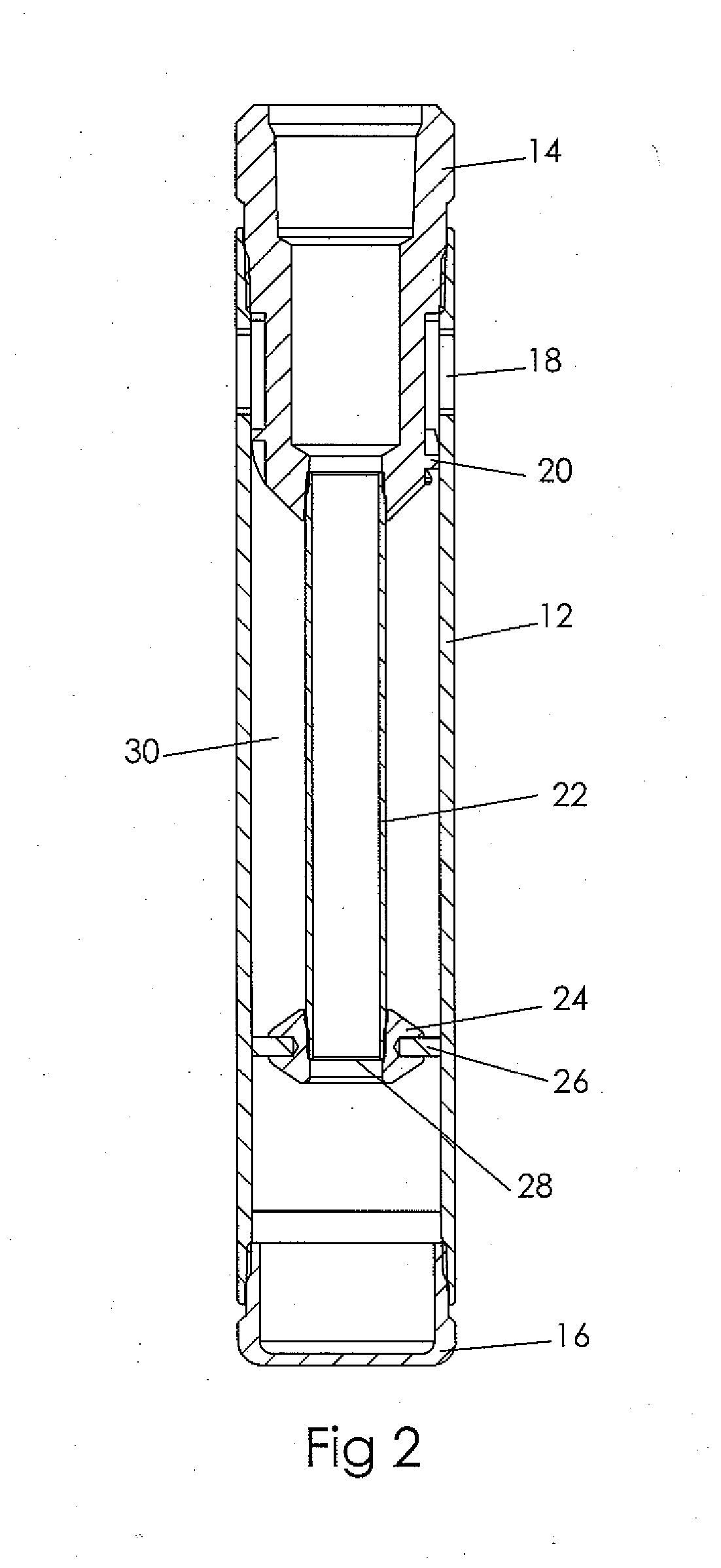
[0014]FIG. 2 is a cross-sectional view of the separator shown in FIG. 1, and depicts the interconnection between the coupling 14 and the housing 12. A vortex flow igniter or spiral gas separator 20 is provided at the low...


PUM


Abstract

A downhole separator (10) separates gas from well fluids which are pumped intermittently to the surface. The separator includes an outer tubular housing (12) and an inner flow tube (22) for passing well fluids to the surface after separation of the gas from the well fluids. A vortex flow generator or spiral gas separator (20) imparts a helical flow to effect separation of the gas from the well fluids. Gas from the gas chamber flows upward past the vortex flow generator when the pump is not pumping well fluids to the surface.

Description

FIELD OF THE INVENTION[0001]The present invention relates to a downhole gas separator of a type used in oil and gas wells to remove gas from well fluids before entering a reciprocating beam rod pump. In one embodiment, the invention relates to a combined gas separator and desander for removing both gas and solid particles from the well fluids before entering the pump.BACKGROUND OF THE INVENTION[0002]Various types of gas separators have been devised to reduce or eliminate gas from a fluid stream before entering a downhole pump which pumps liquids to the surface. Most wells are pumped by a reciprocating beam pump, which has a lift cycle followed by a plunger return cycle, so that liquids are intermittently pumped to the surface during the lift cycle.[0003]Most wells contain both gas and sand or other solid particles, and both gas and sand are preferably reduced or eliminated so that they do not enter the intake to the pump, thereby prolonging the life and improving the efficiency of t...

Claims


Application Information

Patent Timeline
Patent Type & Authority Applications(United States)
IPC IPC(8): E21B43/38
CPCE21B43/38E21B43/127
Inventor COBB, DELWIN E.ARTERBURY, ROY
Owner COBB DELWIN E
Why Eureka
Try Eureka