Delivery unit for an anode circuit of a fuel cell system for delivering a gaseous medium

a fuel cell and anode circuit technology, applied in the direction of liquid fuel engines, separation processes, electrochemical generators, etc., can solve the problems of large surface area in relation to structural space and/or geometrical volume, large surface area, and large volume of structural space, so as to improve the efficiency of the separator, improve the discharge of heavy constituents, and improve the effect of evacuation

Pending Publication Date: 2022-03-31
ROBERT BOSCH GMBH
View PDF3 Cites 0 Cited by
  • Summary
  • Abstract
  • Description
  • Claims
  • Application Information

AI Technical Summary

Benefits of technology

[0021]According to one advantageous embodiment, a shut-off valve is situated in the discharge channel, wherein the at least indirect fluidic connection between the recirculation blower and the separator can be opened or closed by means of the shut-off valve. In this way, the advantage can be achieved that an improved discharge of the heavy constituents out of the collecting vessel of the separator can be achieved by virtue of the shut-off valve being opened or closed as required. Here, on the one hand, the shut-off valve can remain closed in order to prevent that, when the discharge valve is open, the gaseous medium escapes from the recirculation blower via the discharge channel into the collecting vessel, wherein, in particular, H2 is prevented from escaping. On the other hand, it is however also possible for the shut-off valve to be opened such that a pressure and / or volume flow out of the recirculation blower, in particular out of the separation space, can be utilized for better evacuation and for the improved discharge of the heavy constituents from the collecting vessel. In this way, the efficiency of the separator can be improved and / or the degree of separation of H2O and / or N2 with respect to the gaseous medium and / or H2 can be increased, whereby the efficiency of the fuel cell system as a whole can be increased.
[0022]According to one particularly advantageous embodiment, a first sensor arrangement and / or a second sensor arrangement are connected to a control device, wherein, in particular, the first sensor arrangement continuously detects parameters of the separator and the second sensor arrangement continuously detects parameters of the recirculation blower, wherein the control device controls the opening and closing of the discharge valve and / or of the shut-off valve in particular on the basis of the parameters detected by the respective sensor arrangement. In this way, the advantage can be achieved that, by means of the actuation, in particular the opening and closing, of the discharge valve and / or of the shut-off valve on the basis of the data detected by the sensor arrangement, the heavy constituents can be discharged out of the anode circuit of the fuel cell system and / or the separation space and / or the collecting vessel as far as possible whenever a certain concentration of heavy constituents in the gaseous medium is detected by means of the sensor arrangement, and / or if a certain pressure level and / or temperature level is detected and / or overshot in various regions of the fuel cell system, in particular in the collecting vessel or in the separating space. Furthermore, a possibly prevailing pressure gradient and / or a flow and / or a mass flow out of the anode circuit, in particular the delivery unit and / or the recirculation blower and / or a first connecting line and / or a second connecting line, can be utilized to discharge the heavy constituents out of the anode circuit in the most efficient manner possible and at least approximately without additional expenditure of energy, and / or to effect a corresponding separation. The efficiency of the fuel cell system can be increased in this way.

Problems solved by technology

Here, on the one hand, numerous flow diversions and thus flow losses arise, in particular in all three dimensions in space.
Furthermore, the connection of the components of the delivery unit by means of pipelines is disadvantageous insofar as, over the service life of the delivery unit, in particular in the event of intense temperature fluctuations, the pipelines can lead to leak-tightness problems, in particular in the case of welded pipelines.
On the other hand, as a result of the arrangement of the individual components as, at least in part, separate assemblies, there is the disadvantage that, overall, these form a large surface area in relation to the structural space and / or geometrical volume.
This promotes rapid cooling of the components recirculation blower and / or jet pump and / or dosing valve, in particular when the vehicle as a whole is at a standstill for long periods of time, which can lead to increased formation of ice bridges and thus increased damage to the components and / or to the fuel cell system as a whole, which in turn can lead to reduced reliability and / or service life of the delivery unit and / or of the fuel cell system.
A further disadvantage is furthermore a poor cold-start characteristic of the delivery unit and / or of the fuel cell system and / or of the vehicle as a whole, because heating energy and / or thermal energy must be introduced in each case individually into the components recirculation blower and / or jet pump and / or dosing valve, wherein the components are arranged remote from one another and thus each component must be separately heated, in particular in the presence of temperatures below 0° Celsius, in order to eliminate possible ice bridges.

Method used


Image

  • Delivery unit for an anode circuit of a fuel cell system for delivering a gaseous medium
  • Delivery unit for an anode circuit of a fuel cell system for delivering a gaseous medium
  • Delivery unit for an anode circuit of a fuel cell system for delivering a gaseous medium

Examples


Embodiment Construction

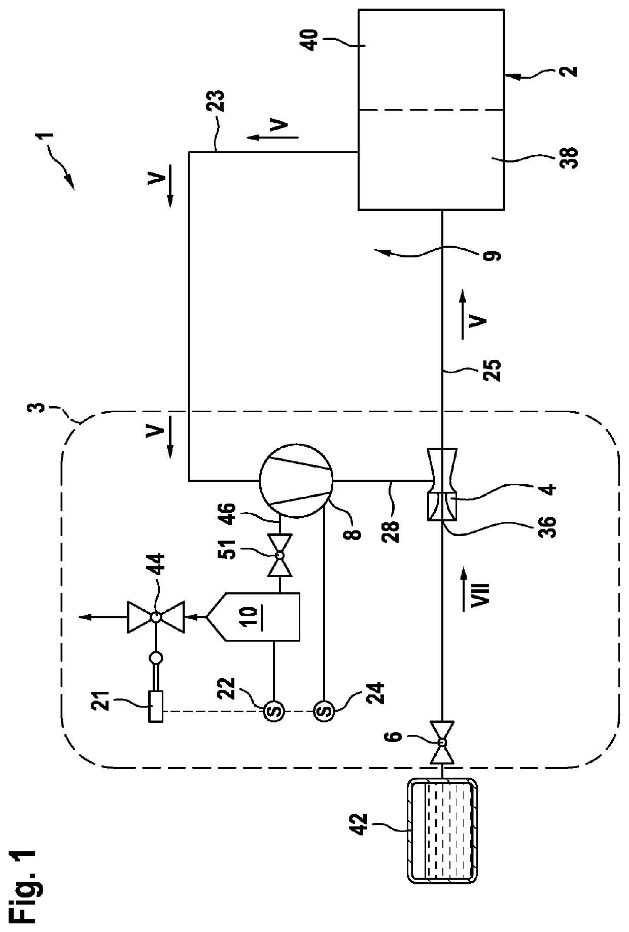
[0032]FIG. 1 is a schematic illustration of a fuel cell system 1 according to the invention with a delivery unit 3.

[0033]Here, it is shown in FIG. 1 that the fuel cell system 1 has a fuel cell 2, wherein the fuel cell 2 has an anode region 38 and a cathode region 40. Here, the anode region 38 of the fuel cell 2 is connected to an anode circuit 9, wherein the anode circuit 9 has the delivery unit 3 and a tank 42.

[0034]Here, the anode region 38 is fluidically connected to the delivery unit 3 by means of a first connecting line 23, wherein the gaseous medium flows in a flow direction V from the anode region 38 to the delivery unit 3. Here, the delivery unit is fed not only with the recirculate flowing from the anode region 38 of the fuel cell 2 but additionally with a motive medium from the tank 42. After flowing through the delivery unit 3, the gaseous medium that is composed of the recirculate and the motive medium flows in a flow direction V via a second connecting line 25 back to t...


PUM

PropertyMeasurementUnit
pressureaaaaaaaaaa
pressureaaaaaaaaaa
axis of rotationaaaaaaaaaa

Abstract

Disclosed is a delivery unit (3) for an anode circuit (9) of a fuel cell system (1) for delivering a gaseous medium, in particular hydrogen, from an anode region (38) of a fuel cell (2), said delivery unit (3) comprising at least one recirculation fan (8) and being at least indirectly fluidically connected to the outlet of the anode region (38) by means of at least one connection line (23) and being fluidically connected to the inlet of the anode region (38) by means of an additional connection line (25). According to the invention, in addition to the recirculation fan (8), the delivery unit (3) comprises a jet pump (4), a metering valve (6) and a separator (10) as other components, and the flow contours of the components (4, 6, 8, 10) for the gaseous medium are at least almost entirely arranged in a common housing (7).

Description

BACKGROUND OF THE INVENTION[0001]The present invention relates to a delivery unit for an anode circuit of a fuel cell system for delivering a gaseous medium, in particular hydrogen, which is provided in particular for use in vehicles with a fuel cell drive. The invention furthermore relates to a fuel cell system having a delivery unit of said type.[0002]In the automotive sector, in addition to liquid fuels, gaseous fuels will also play an increasing role in the future. In particular in the case of vehicles with a fuel cell drive, it is necessary for hydrogen gas flows to be controlled. Here, the gas flows are no longer controlled discontinuously, as in the case of the injection of liquid fuel, but the gas is extracted from at least one high-pressure tank and is conducted via an inflow line of a medium-pressure line system to the delivery unit. Said delivery unit conducts the gas via a connecting line of a low-pressure line system to a fuel cell.[0003]DE 10 2011 105 710 B4 has disclo...

Claims


Application Information

Patent Timeline
Patent Type & Authority Applications(United States)
IPC IPC(8): H01M8/04119H01M8/04746F04F5/24H01M8/04228
CPCH01M8/04164H01M8/04753H01M2250/20H01M8/04228F04F5/24H01M8/04097H01M8/04156Y02T10/70Y02E60/50F04D29/706F04D23/008H01M8/0662B01D53/24B01D2256/16B01D2257/102B01D2257/80
Inventor HERO, ALEXANDERMERZ, ARMIN
Owner ROBERT BOSCH GMBH
Why Eureka
Try Eureka