Airship, anchoring device, and landing and mooring method

a technology for anchoring devices and airships, applied in the direction of rigid airships, lighter-than-air aircraft, hybrid airships, etc., can solve the problems of increasing the lift of the envelope, lowering the airship to the vertical, and altering the angle of attack, so as to facilitate landing and mooring

Active Publication Date: 2014-06-12
DIRISOLAR
View PDF6 Cites 7 Cited by
  • Summary
  • Abstract
  • Description
  • Claims
  • Application Information

AI Technical Summary

Benefits of technology

[0013]This upward force is exerted firstly on the front portion of the envelope, thus creating a pulling-up torque which alters the angle of attack and therefore the overall stability of the envelope, in an irregular and unpredictable way. Often, this change in angle of attack increases the lift of the envelope and tends to move the airship farther away from the ground. In certain cases, this pulling-up torque can thus increase of its own accord under the effect of the wind, creating an unstable situation that can sometimes even raise the airship to the vertical, or even overturn it completely.
[0091]It should be noted in particular that this flexibility of use as well as the range of meteorological conditions offer very interesting advances relative to the current possibilities according to the prior art, and are sufficient to allow radical development of the possibilities of use and of the industrial and commercial markets for this type of aircraft.

Problems solved by technology

However, at the end of the approach but before being sufficiently low to permit autonomous mooring or disembarkation, for example below ten to twenty metres for the bottom of the envelope, closing of this same zone between the ground and the envelope finally causes compression phenomena, which exert a torque and an upward force, thus opposing the downward force.
This upward force is exerted firstly on the front portion of the envelope, thus creating a pulling-up torque which alters the angle of attack and therefore the overall stability of the envelope, in an irregular and unpredictable way.
Often, this change in angle of attack increases the lift of the envelope and tends to move the airship farther away from the ground.
In certain cases, this pulling-up torque can thus increase of its own accord under the effect of the wind, creating an unstable situation that can sometimes even raise the airship to the vertical, or even overturn it completely.
Even once firmly moored on the ground, these forces can sometimes be enough to break or pull away this mooring, often leading to loss or destruction of the aircraft.

Method used


Image

  • Airship, anchoring device, and landing and mooring method
  • Airship, anchoring device, and landing and mooring method
  • Airship, anchoring device, and landing and mooring method

Examples


Embodiment Construction

of an Aircraft

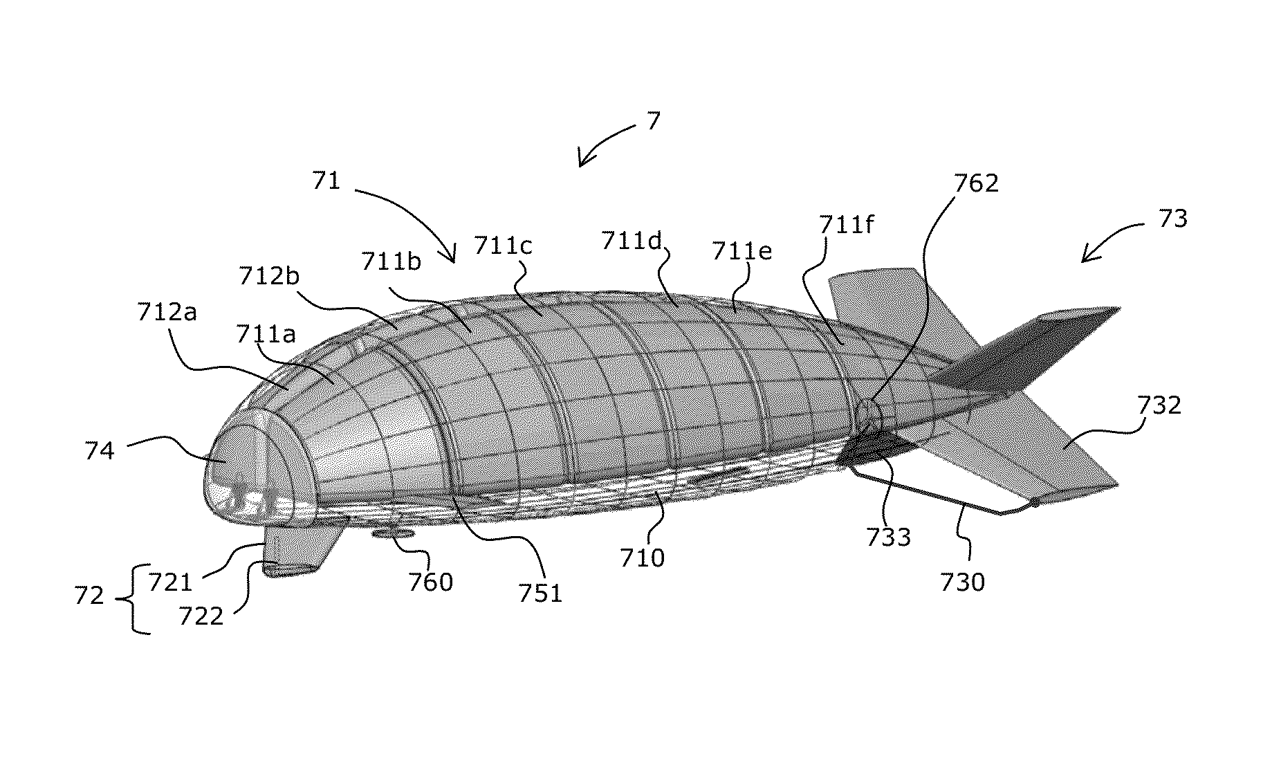
[0116]Exploiting the possibilities of the invention, an example of a small aircraft for two persons is described here, complying with the French standards of the regulatory category of machines of the Ultra Light Motorized (ULM) type, in its preliminary definition.

[0117]In this context, such an aircraft is envisaged with the following characteristics:[0118]Rigid shell, with cells containing helium without increased pressure[0119]On-board energy: batteries+photovoltaic panels

[0120]Stabilizers and Controls Adopted[0121]Four fixed tail units, in X configuration, for their quality as stabilizers, and in particular providing vertical stabilizer function;[0122]Three propellers: 2 for forward and yaw, 1 for lift;[0123]Pitch control with two forward control surfaces called “canard”, preferably coupled together;[0124]A retractable punch behind the anchoring cabin;[0125]Longitudinal displacement of the batteries for correcting attitude in flight, and ballasting of the back on th...


PUM


Abstract

An air vehicle such as an airship is provided, having a rounded top portion, and the bottom portion of which has a substantially planar shape, including a region having a smaller inclination, which is referred to as a bottom surface, and the surface area of which is larger than that of an intermediate region having a greater inclination, referred to as an intermediate surface. The general shape produces, due to relative wind, a resulting overall downward force near the ground. The vehicle also includes a device for anchoring same to the ground, the anchoring device being stationary or controllable from the vehicle, located at the front portion of the vehicle, and projecting downward, in particular a ram including a portion which can be expanded by applying a bar against a translatably movable shoulder. Also included is a landing method implementing such a vehicle.

Description

[0001]The present invention relates to an aircraft of the airship type, which has a bottom face of flat shape and is of a general shape designed to produce, under the effect of relative wind, an overall downward resultant force when close to the ground. According to the invention, this aircraft further comprises a device for anchoring to the ground, fixed or maneuverable from said aircraft, which is located in the front portion of said aircraft and extends downwards, in particular a rigid fixing punch, comprising a part that is expandable by a ramp bearing against a nut displaced in translation.[0002]The invention also relates to a method of landing using such an aircraft. This method comprises, under the effect of the downward force with compensation by maintaining a nose-up attitude, a descending flight until there is contact of a rear portion of the aircraft; followed by a decrease in nose lift until the anchoring device makes contact with the ground, in particular with the drivi...

Claims


Application Information

Patent Timeline
Patent Type & Authority Applications(United States)
IPC IPC(8): B64B1/00
CPCB64B1/005B64B1/00B64B1/20B64B1/66B64B2201/00
Inventor TIXIER, PHILIPPE
Owner DIRISOLAR
Why Eureka
Try Eureka