Sheet conveying apparatus and image forming apparatus
a technology of conveying apparatus and sheet, which is applied in the direction of transportation and packaging, electrographic process, instruments, etc., can solve the problems of sheet damage, jam, and variation of the conventional switching operation of the switching member, and achieve the effect of simple and inexpensive configuration
- Summary
- Abstract
- Description
- Claims
- Application Information
AI Technical Summary
Benefits of technology
Problems solved by technology
Method used
Image
Examples
first embodiment
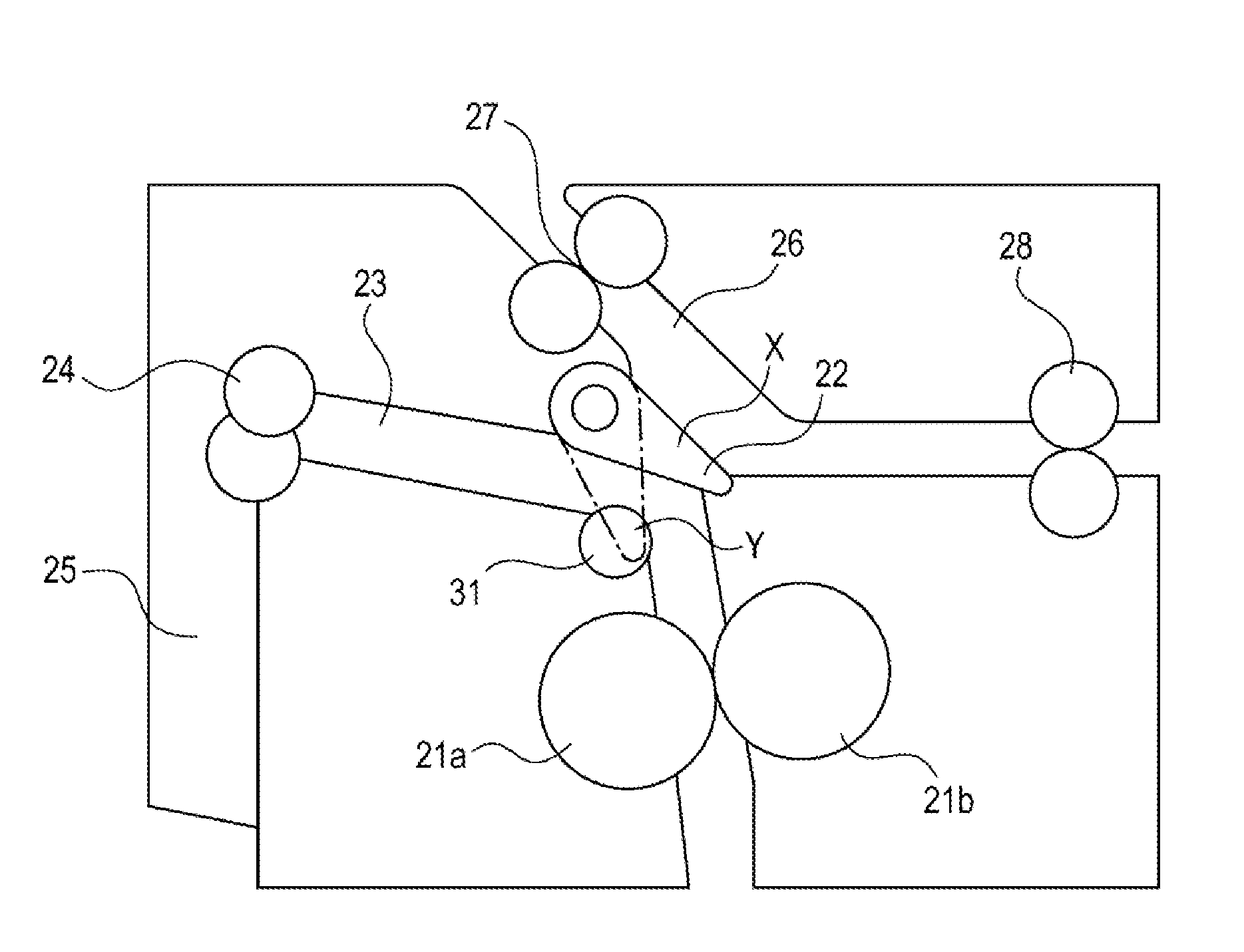
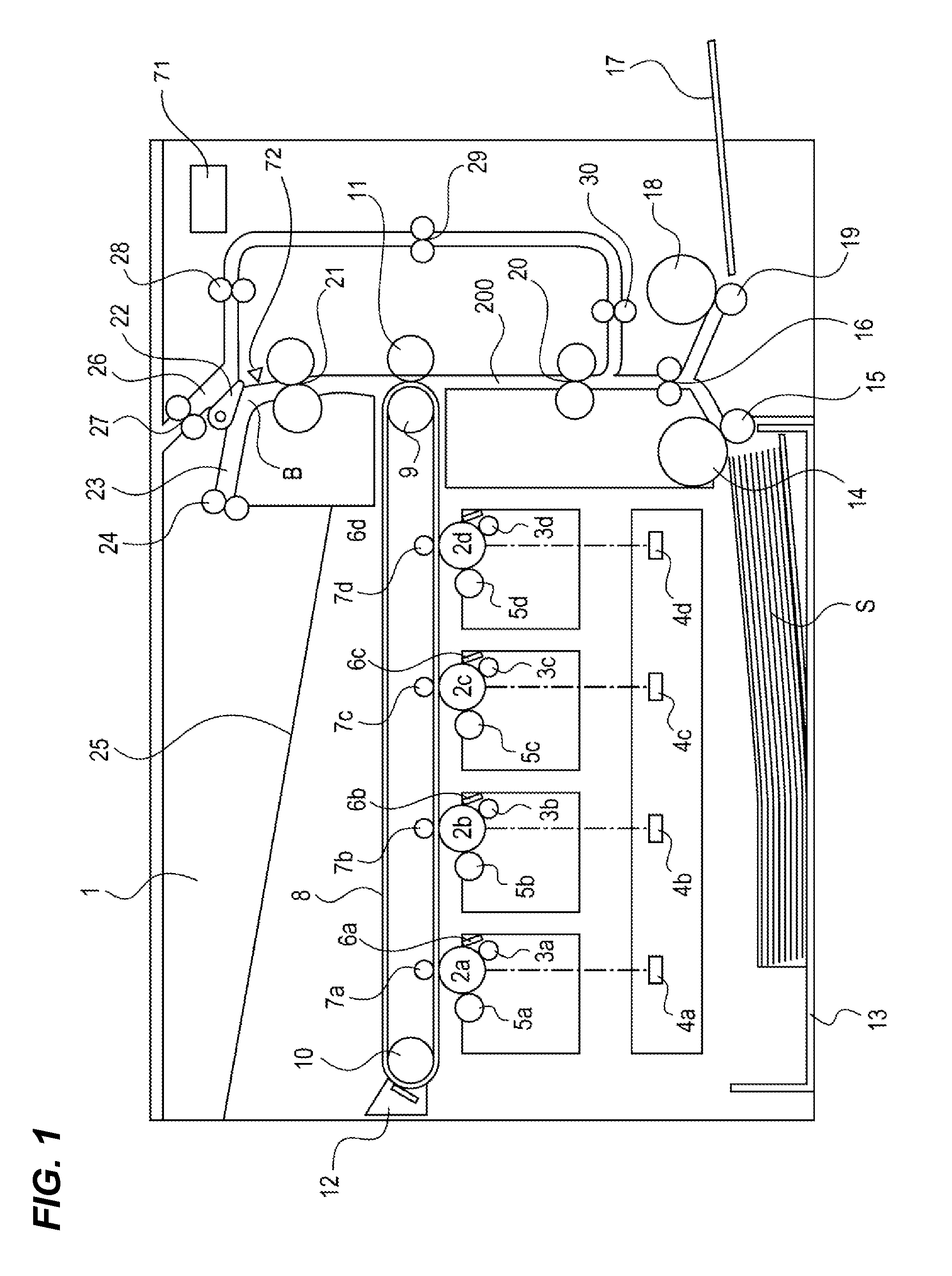
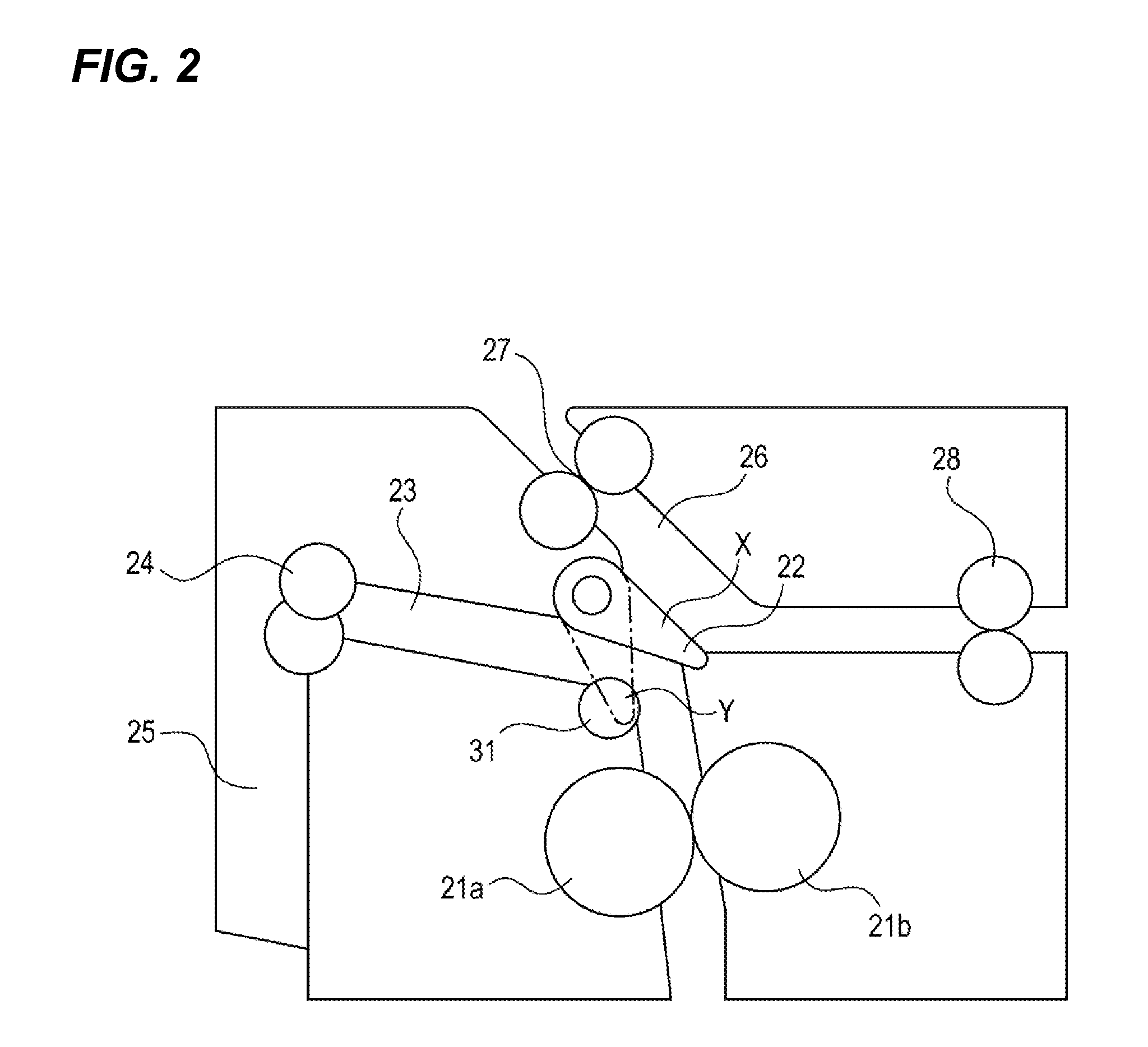
[0034]FIG. 1 is an example of a sheet conveying apparatus according to a first embodiment of the invention and a cross-sectional view illustrating a configuration of an image forming apparatus of a color electrophotographic system, and FIG. 2 is a cross-sectional view illustrating a detailed configuration of a periphery a double-side switching member, which is a conveying path switching member.
Overall Configuration of Image Forming Apparatus
[0035]An image forming apparatus 1 is provided with four drum-shaped image bearing members which are juxtaposedly arranged in a substantially horizontal direction as an image bearing member, that is, photosensitive drums 2 (2a, 2b, 2c, and 2d). The photosensitive drum 2 is rotationally driven in a clockwise direction in FIG. 1.
[0036]In addition, a charging device 3 (3a, 3b, 3c, and 3d) is provided to uniformly charge a surface of the photosensitive drum 2. Moreover, a scanner unit 4 (4a, 4b, 4c, and 4d) is provided to form an electrostatic latent...
second embodiment
[0098]Another embodiment of the invention will be described below with reference to FIGS. 9 to 11. A configuration of an image forming apparatus in the second embodiment is the same as that in the first embodiment, and the same or similar components as those in the first embodiment are denoted by the same reference numerals and the repeated description will not be presented. Hereinafter, parts different from the first embodiment will be mainly described.
[0099]FIG. 9 is a diagram illustrating a detailed switching configuration of the double-side switching member 22 of the image forming apparatus 1 according to the second embodiment. A switching member return compression spring 60 is an unequal pitch spring, and a pitch is different in the middle of spring. A compression spring holding portion 61 is provided in a part of the sheet guide portion of the reverse conveying path 26 (FIGS. 7A to 7C) to hold the switching member return compression spring 60.
[0100]Arrows in FIG. 9 illustrate ...
third embodiment
[0112]Next, further another embodiment of the invention will be described with reference to FIGS. 13 to 16. A configuration of an image forming apparatus in a third embodiment is the same as that in the first embodiment, and the same or similar components as those in the first embodiment are denoted by the same reference numerals and the repeated description will not be presented. Hereinafter, parts different from the first embodiment will be mainly described.
[0113]FIG. 13 is a diagram illustrating a detailed switching configuration of the double-side switching member 22 according to a third embodiment.
[0114]A switching member abutting portion 62a of a cam-attached connection plate 62 abuts on the arm portion 22a of the double-side switching member 22. A cam 63 (cam-shaped member) is pressed against the cam-attached connection plate 62 side by a cam pressure spring 64. In addition, the cam pressure spring 64 is held by a pressure spring holding portion 65. Further, the cam-attached ...
PUM
| Property | Measurement | Unit |
|---|---|---|
| driving force | aaaaa | aaaaa |
| driving force | aaaaa | aaaaa |
| force | aaaaa | aaaaa |
Abstract
Description
Claims
Application Information
 - R&D
- Intellectual Property
- Life Sciences
- Materials
- Tech Scout
- Unparalleled Data Quality
- Higher Quality Content
- 60% Fewer Hallucinations
Browse by: Latest US Patents, China's latest patents, Technical Efficacy Thesaurus, Application Domain, Technology Topic, Popular Technical Reports.
© 2025 PatSnap. All rights reserved.Legal|Privacy policy|Modern Slavery Act Transparency Statement|Sitemap|About US| Contact US: help@patsnap.com


