Dual Mode Wireless Power Receiver

a wireless power receiver and dual-mode technology, applied in the direction of electrical apparatus construction details, transportation and packaging, support structure mounting, etc., can solve the problems of increasing the cost of parallel approach, increasing the cost of implementation, and reducing the transmission power, so as to increase the transmission power and reduce the transmission power

Active Publication Date: 2014-06-12
WIPQTUS
View PDF3 Cites 87 Cited by
  • Summary
  • Abstract
  • Description
  • Claims
  • Application Information

AI Technical Summary

Benefits of technology

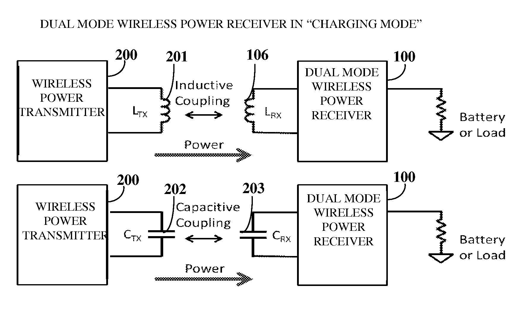
[0012]Depending on the type of the secondary wireless power receiver, the dual mode wireless power receiver authenticates, decrypts, and encrypts a data transfer between the dual mode wireless power receiver and the secondary wireless power receiver via the identified wireless power protocol. If the secondary wireless power receiver is a non-authenticating secondary wireless power receiver, the dual mode wireless power receiver receives and interprets the data from the secondary wireless power receiver in the identified wireless power protocol without authentication and / or encryption. If the secondary wireless power receiver is a one-way authenticating secondary wireless power receiver, the dual mode wireless power receiver provides authentication information to the one-way authenticating secondary wireless power receiver to enable the authentication of the dual mode wireless power receiver, receives, decrypts and interprets the data from the one-way authenticating secondary wireless power receiver and responds with suitable encrypted data to the one-way authenticating secondary wireless power receiver in the identified wireless power protocol. If the secondary wireless power receiver is a two-way authenticating secondary wireless power receiver, the dual mode wireless power receiver initiates exchange of the authentication information between the dual mode wireless power receiver and the two-way authenticating secondary wireless power receiver to authenticate the dual mode wireless power receiver and the two-way authenticating secondary wireless power receiver, receives, decrypts and interprets the data from the two-way authenticating secondary wireless power receiver and responds with suitable encrypted data to the two-way authenticating secondary wireless power receiver in the identified wireless power protocol. If the secondary wireless power receiver is a power sinking secondary wireless power receiver, the dual mode wireless power receiver on receiving a request from the secondary wireless power receiver, interprets the received request and performs a function associated with the transmitted power. The function performed may include one of increase the transmitted power, decrease the transmitted power, maintain the transmitted power, turn off the transmitted power, etc. The dual mode wireless power receiver takes action as per the wireless power protocol to effectively transmit power to the secondary wireless power receiver.

Problems solved by technology

When traveling on business or on a vacation, it is very cumbersome to carry the many disparate power adapters for each of the mobile devices.
Such a parallel approach is too costly particularly for mobile devices catering to the mid and lower tiers of the market.
The software application implementations may or may not offer security features and that could compromise sensitive user information.

Method used


Image

  • Dual Mode Wireless Power Receiver
  • Dual Mode Wireless Power Receiver
  • Dual Mode Wireless Power Receiver

Examples


first embodiment

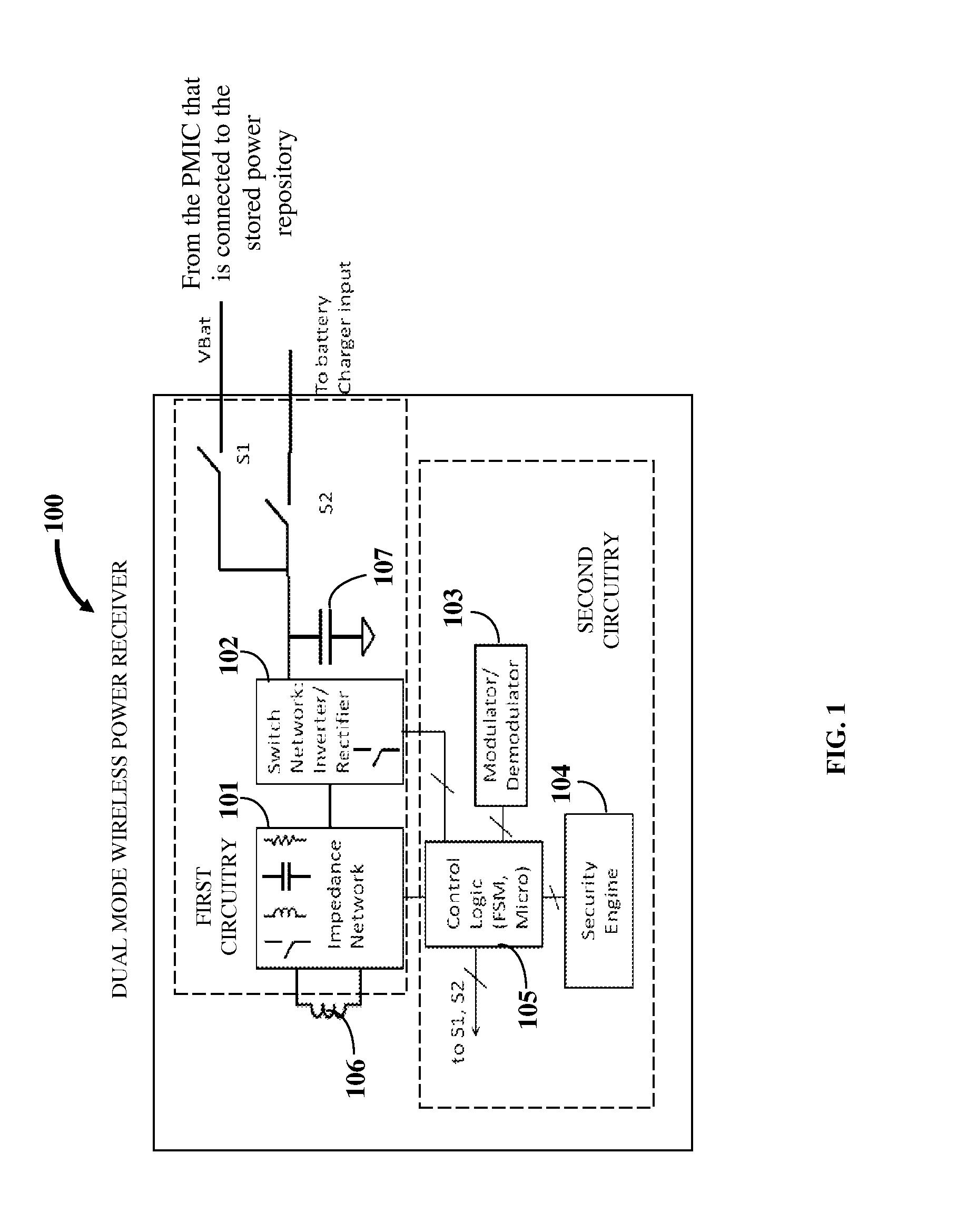
[0053]FIG. 7A exemplarily illustrates the switch network 102 of the dual mode wireless power receiver 100 exemplarily illustrated in FIG. 3, in the communication mode. In the communication mode, the switch network 102 can be configured as a full bridge inverter by keeping switch S1a in an on state and driving switches S3, S4, S5, and S6 as per the timing relationship exemplarily illustrated in FIG. 7A. As exemplarily illustrated by the timing relationship waveform in FIG. 7A, switches S3 and S6 are driven on when the switches S4 and S5 are driven off and vice versa. In communication mode, switch S2 which is external to the switch network 102 is configured in an off state to ensure that the stored power is not recirculated as that would be very wasteful. Switch S1 which is external to the switch network 102 is configured in an on state to enable the switch network 102 to draw stored power via the power management integrated circuit (PMIC).

second embodiment

[0054]FIG. 7B exemplarily illustrates the switch network 102 of the dual mode wireless power receiver 100 exemplarily illustrated in FIG. 3, in the communication mode. The switch network 102 is configured as half bridge inverter by keeping switch S5 in an off state and switches S1a and S6 in an on state. Switches S3 and S4 are driven with the timing relationship exemplarily illustrated in FIG. 7B. Alternatively the switch network 102 can be configured as a half bridge inverter by keeping switch S3 in an off state and switches S1a and S4 in an on state. Switches S5 and S6 would be driven analogous to the timing relationship exemplarily illustrated in FIG. 7B with S5 substituting for S3 and S6 substituting for S4. In both these embodiments, switch S2 which is external to the switch network 102 is configured in an off state to ensure that the stored power is not recirculated as that would be very wasteful. Switch S1 which is external to the switch network 102 is configured in an on sta...


PUM


Abstract

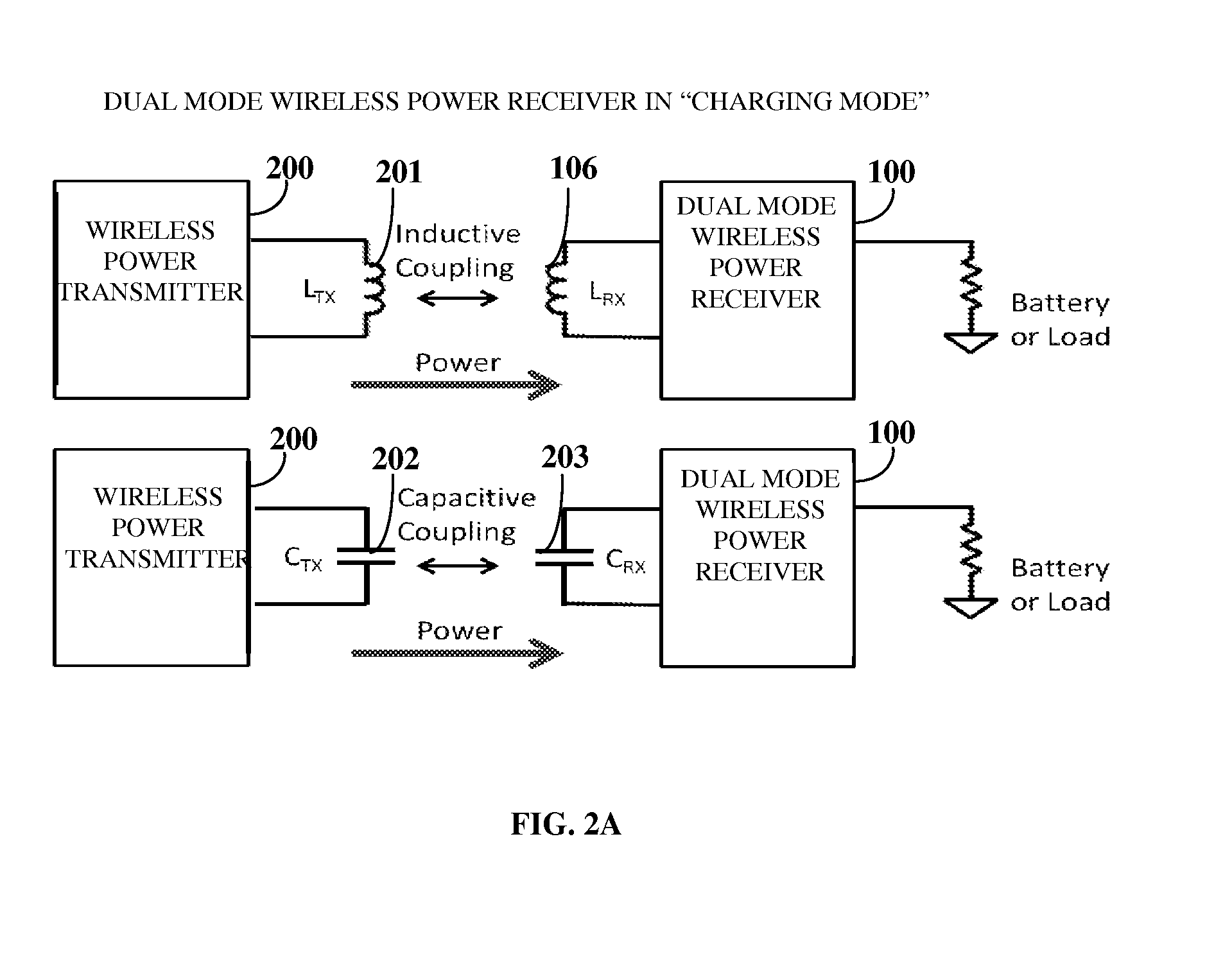
A dual mode wireless power receiver (DMWPR) selectively applying a received power to a load device and utilizing at least a part of the power to power-up, communicate, and charge a secondary wireless power receiver (SWPR) is provided. The DMWPR includes a first circuitry having an impedance network, a switch network, a filter capacitor, and one or more switches, and a second circuitry having a security engine, a control logic circuit, and a modulator/demodulator circuit. The first circuitry receives power in charging mode and transmits power in communication mode. The second circuitry configures the first circuitry to allow receipt and transmission of power, receives and interprets data from SWPR in the identified wireless power protocol, and based on the type of SWPR authenticates, decrypts, and encrypts data transfer between DMWPR and SWPR, and receives and executes on a request from SWPR to perform a function associated with transmitted power.

Description

CROSS REFERENCE TO RELATED APPLICATIONS[0001]This application claims the benefit of provisional patent application No. 61 / 682,312 titled “Dual Mode Wireless Charging Receiver”, filed in the United States Patent and Trademark Office on Aug. 13, 2012.[0002]The specification of the above referenced patent application is incorporated herein by reference in its entirety.BACKGROUND[0003]When traveling on business or on a vacation, it is very cumbersome to carry the many disparate power adapters for each of the mobile devices. One would rather carry a wireless power pad, if the wireless power pad could charge multiple devices. Such a multi-device charging wireless power pad would certainly be more convenient, however it is an extra piece of luggage that the user would have to remember and carry. It would be even more convenient if mobile devices with big battery capacity such as a notebook, tablet, etc., that typically are carried along on the trips, were able to wirelessly charge other lo...

Claims


Application Information

Patent Timeline
Patent Type & Authority Applications(United States)
IPC IPC(8): H02J17/00H02J7/02
CPCH02J7/0068H04B5/0037H02J50/10H02J50/05H02J50/80H02J50/12
Inventor SANKAR, GANAPATHYSINGH, MANJIT
Owner WIPQTUS
Why Eureka
Try Eureka