Buck power converter

Inactive Publication Date: 2014-06-12
EXCELLIANCE MOS
View PDF3 Cites 5 Cited by
  • Summary
  • Abstract
  • Description
  • Claims
  • Application Information

AI Technical Summary

Benefits of technology

The invention is a circuit that prevents ringing in a power transistor when a buck power converter is running in a light-load mode. A current flows through an inductor in the converter and can cause ringing. The anti-ringing circuit uses a diode to clamp a voltage swing and reduce this noise. The technical effect is that the circuit prevents ringing and reduces noise in the buck power converter.

Problems solved by technology

After the current on the inductor L1 is gradually reduced to 0, the voltage VB on a terminal where the power transistor Q1 and the inductor L1 are coupled may encounter the ringing issue; thus generating unnecessary noise.

Method used


Image

  • Buck power converter
  • Buck power converter
  • Buck power converter

Examples


Embodiment Construction

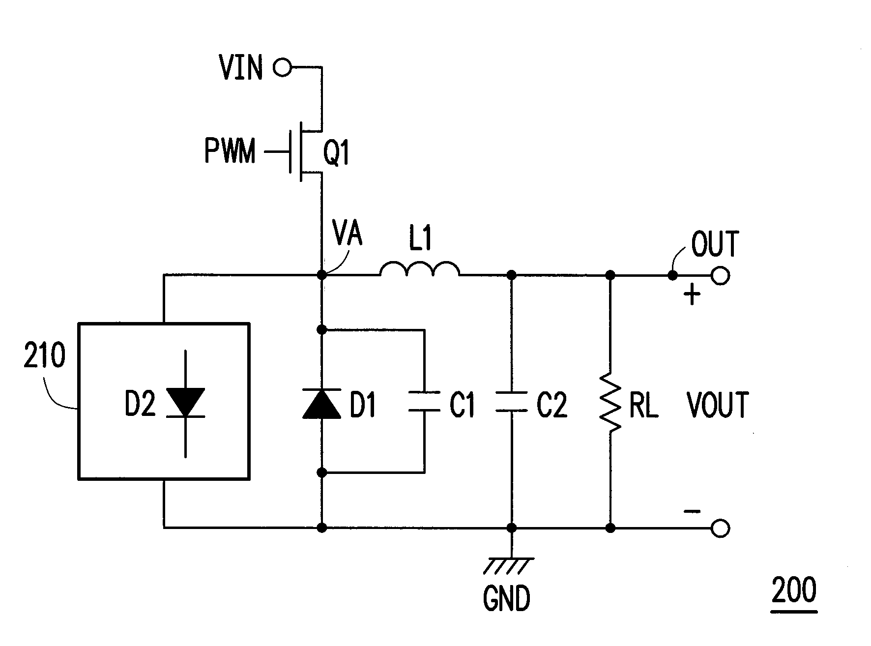
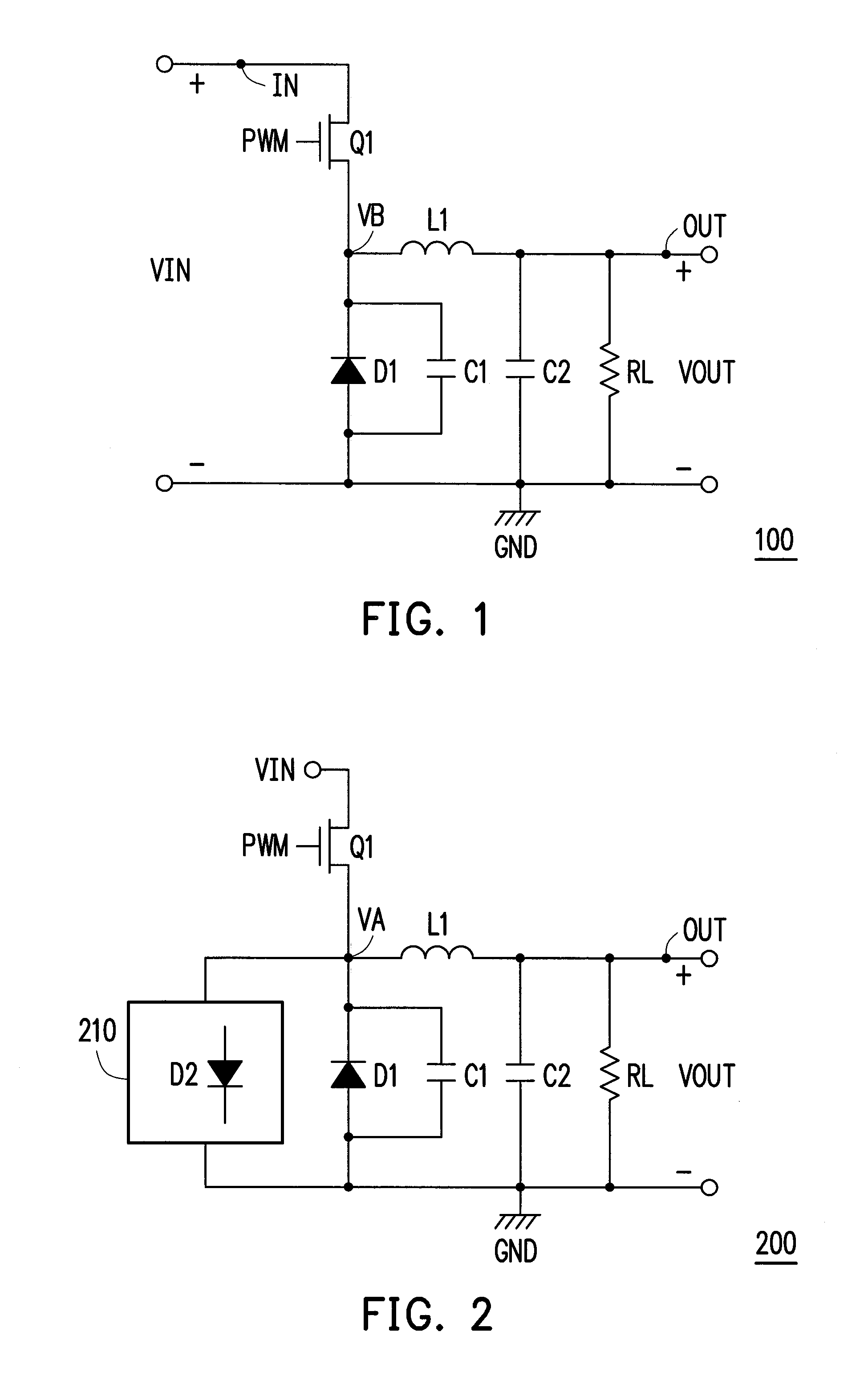
[0023]Please refer to FIG. 2, which schematically illustrates a buck power converter 200 according to an embodiment of the invention. The buck power converter 200 includes a power transistor Q1, an inductor L1, a diode D1, and an anti-ringing circuit 210. The power transistor Q1 has a first terminal (e.g. a source), a second terminal (e.g. a drain), and a control terminal (e.g. a gate). The first terminal of the power transistor Q1 receives an input voltage VIN, and the control terminal of the power transistor Q1 receives a pulse width modulation signal PWM. According to the pulse width modulation signal, the power transistor Q1 is switched on or off. The second terminal of the power transistor Q1 is coupled to one terminal of the inductor L1, and the other terminal of the inductor L1 is coupled to an output terminal OUT of the buck power converter 200, so as to generate an output voltage VOUT.

[0024]The diode D1 is serially coupled between the second terminal of the power transistor...


PUM


Abstract

A buck power converter includes a power transistor, an inductor, a first diode, and an anti-ringing circuit. The power transistor has a first terminal, a second terminal, and a control terminal. The first terminal of the power transistor receives an input voltage, and the control terminal of the power transistor receives a pulse width modulation (PWM) signal. The anti-ringing circuit detects a detection voltage on the second terminal of the power transistor. According to the detection voltage, the anti-ringing circuit provides at least one second diode serially coupled between the second terminal of the power transistor and a reference ground terminal in a forward-biased manner, so as to clamp a voltage swing of the detection voltage.

Description

BACKGROUND OF THE INVENTION[0001]1. Field of Invention[0002]This invention relates to a buck power converter, and more particularly to a buck power converter capable of achieving an anti-ringing effect.[0003]2. Description of Related Art[0004]FIG. 1 illustrates circuitry of a conventional buck power converter 100. The buck power converter 100 includes a power transistor Q1, a diode D1, an inductor L1, and capacitors C1 and C2, and the buck power converter 100 generates an output voltage VOUT according to an input voltage VIN received by the buck power converter 100, so as to drive a load RL.[0005]The power transistor Q1 is switched on or off according to a pulse width modulation signal PWM received by the power transistor Q1. In the process of switching on or off the power transistor Q1, the buck power converter 100 transmits a current from an input terminal IN that receives the input voltage VIN to an output terminal OUT of the buck power converter 100. When the power transistor Q1...

Claims


Application Information

Patent Timeline
IPC IPC(8): G05F1/10
CPCG05F1/10H02M3/156H02M1/34Y02B70/10H02M1/342
Inventor LIN, PAO-CHUANLIN, SU-YUANCHOU, HUNG-CHE
Owner EXCELLIANCE MOS
Why Eureka
Try Eureka