Plastic lens and lens barrel

Active Publication Date: 2014-06-12
PANASONIC INTELLECTUAL PROPERTY MANAGEMENT CO LTD
View PDF3 Cites 9 Cited by
  • Summary
  • Abstract
  • Description
  • Claims
  • Application Information

AI Technical Summary

Benefits of technology

[0031]The plastic lens according to the present disclosure has excellent optical performance due to less decentering error

Problems solved by technology

If such undesired light reaches an imaging surface, noise such as flare or ghost occurs, and thereby image characteristics are deteriorated.
Also in the case of using such a plastic lens, occurrence of undesired light that causes noise such as flare or ghost needs to be suppressed.
However, in the case of a plastic lens, a coating material for coloring the plastic lens in black is usually highly viscous, and particularly the thickness of a coat

Method used


Image

  • Plastic lens and lens barrel
  • Plastic lens and lens barrel
  • Plastic lens and lens barrel

Examples


embodiment 1

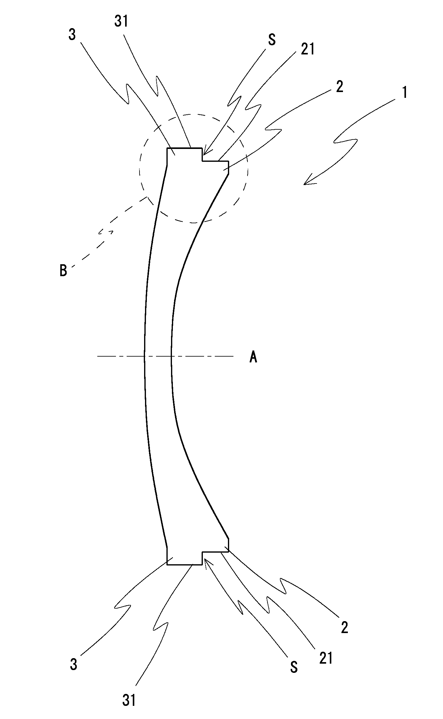
[0040]FIG. 1 is a schematic cross-sectional view of a plastic lens according to Embodiment 1 along a direction parallel to an optical axis.

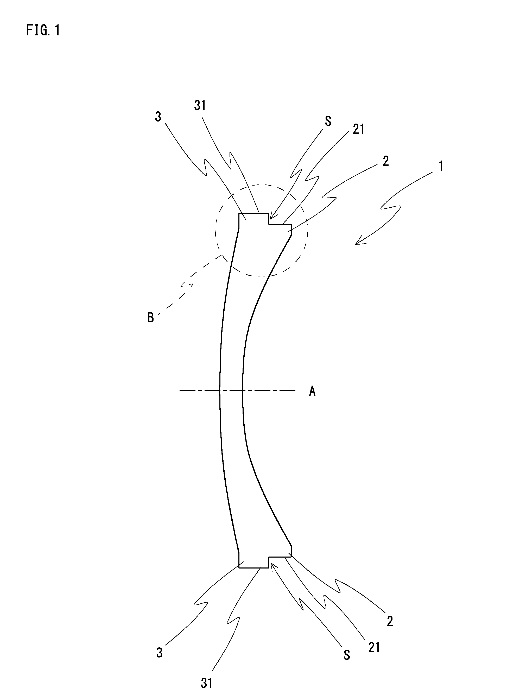
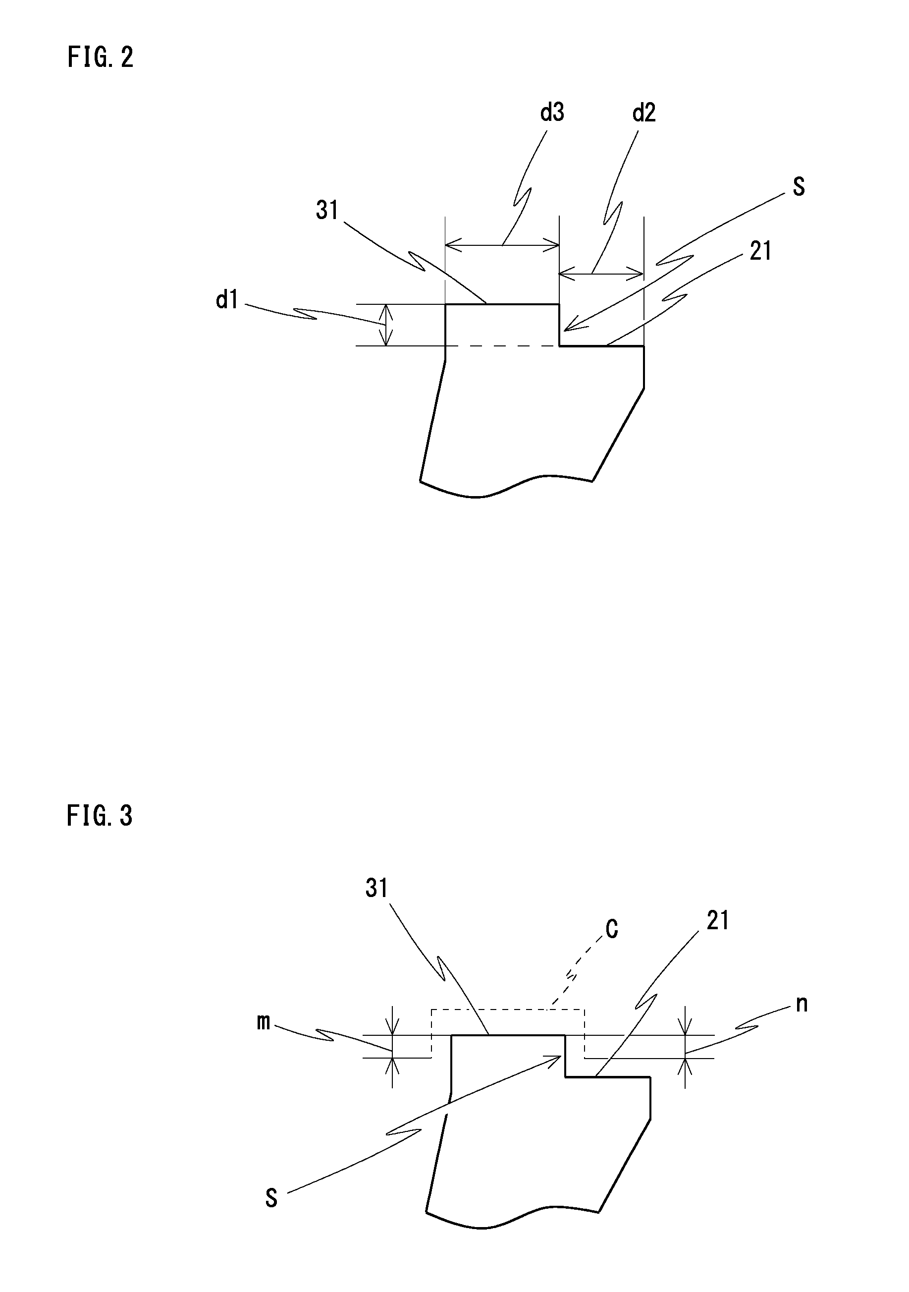
[0041]The plastic lens 1 according to Embodiment 1 is a concave meniscus lens. In FIG. 1, the plastic lens 1 includes a first edge section 2 on a concave surface side, and a second edge section 3 on a convex surface side. The first edge section 2 has a first outer circumferential edge surface 21, and the second edge section 3 has a second outer circumferential edge surface 31. The first outer circumferential edge surface 21 is formed substantially parallel to an optical axis A of the lens. The second outer circumferential edge surface 31 is formed so as to have an outer circumferential step S with respect to the first outer circumferential edge surface 21 in the direction of the optical axis A of the lens. In this way, in the plastic lens 1 according to Embodiment 1, in contrast to conventional plastic lenses each having a tapered portion, a step...


PUM


Abstract

A plastic lens, comprising: a first edge section having a first outer circumferential edge surface formed substantially parallel to an optical axis of the plastic lens; and a second edge section having a second outer circumferential edge surface formed so as to have a step with respect to the first outer circumferential edge surface, wherein the first outer circumferential edge surface is not coated with a black coating material that suppresses internal reflection of light, and at least a portion of the second outer circumferential edge surface is coated with the black coating material that suppresses internal reflection of light.

Description

CROSS-REFERENCE TO RELATED APPLICATION[0001]This application is a Continuation of International Application No. PCT / JP2012 / 005104, filed on Aug. 10, 2012, which in turn claims the benefit of Japanese Application No. 2011-184166, filed on Aug. 25, 2011, the disclosures of which Applications are incorporated by reference herein.BACKGROUND[0002]1. Field[0003]The present disclosure relates to plastic lenses and lens barrels.[0004]2. Description of the Related Art[0005]When a light beam is incident on an imaging optical system composed of a plurality of lenses, such as a zoom lens system or a single focal length lens system, a portion of the incident light is reflected at an inner surface of an outer circumferential part of each lens. Therefore, the reflected light, which is undesired light, might be cast into the range of an aperture for photographing. If such undesired light reaches an imaging surface, noise such as flare or ghost occurs, and thereby image characteristics are deteriora...

Claims


Application Information

Patent Timeline
IPC IPC(8): G02B1/11G02B7/02
CPCG02B1/11G02B3/00G02B7/02G02B7/021G02B7/022G02B27/0018
Inventor MIYAZAKI, KYOICHIHIBINO, YUKIO
Owner PANASONIC INTELLECTUAL PROPERTY MANAGEMENT CO LTD
Why Eureka
Try Eureka