Light emitting apparatus

a technology of light emitting apparatus and light source, which is applied in the direction of lighting and heating apparatus, semiconductor devices for light sources, light source combinations, etc., can solve the problems of relatively low efficiency of optical systems according to the related art, relatively short lifespan of optical systems, and environmental problems, so as to achieve high color rendering properties and improve light emission efficiency

Inactive Publication Date: 2014-06-12
SAMSUNG ELECTRONICS CO LTD
View PDF6 Cites 24 Cited by
  • Summary
  • Abstract
  • Description
  • Claims
  • Application Information

AI Technical Summary

Benefits of technology

[0024]As set forth above, according to exemplary embodiments of the present disclosure, when a light emitting device is used, a combination of a light source and a phosphor may be appropriately employed to a single module, whereby light emission efficiency may be improved and white light having high color rendering properties may be obtained.

Problems solved by technology

In general, as optical systems used for illumination devices or the like, fluorescent lamps and incandescent lamps have been widely used, but mercury used in fluorescent lamps has caused environmental issues.
Further, optical systems according to the related art have a relatively short lifespan and efficiency thereof is relatively low.
Therefore, the use of optical systems according to the related art is not effective in terms of saving power.
Among the three schemes detailed above, in the case of the scheme in which white light is implemented by using blue LEDs as light sources and allowing yellow phosphors to be excited, red light intensity may be deteriorated such that difficulties in terms of color implementation may be present.
However, while these schemes have excellent color implementation, efficiency thereof is degraded.

Method used


Image

  • Light emitting apparatus
  • Light emitting apparatus
  • Light emitting apparatus

Examples


Embodiment Construction

[0031]Exemplary embodiments of the present disclosure will now be described in detail with reference to the accompanying drawings.

[0032]The disclosure may, however, be exemplified in many different forms and should not be construed as being limited to the specific embodiments set forth herein. Rather, these embodiments are provided so that this disclosure will be thorough and complete, and will fully convey the scope of the disclosure to those skilled in the art. In the drawings, the shapes and dimensions of elements may be exaggerated for clarity, and the same reference numerals will be used throughout to designate the same or like elements.

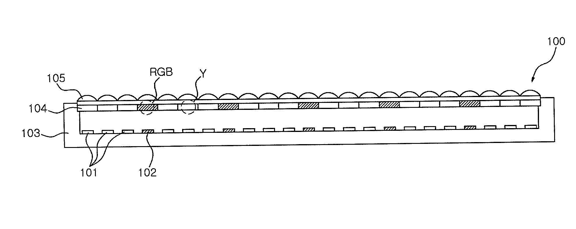
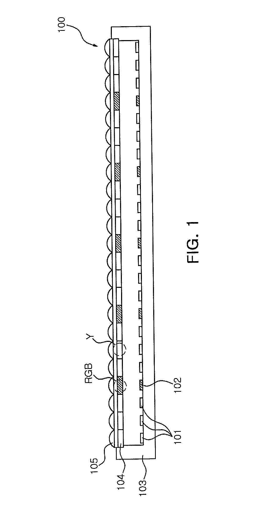
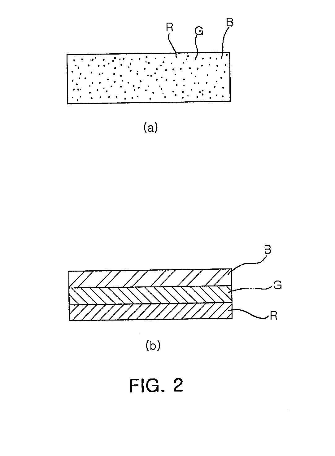
[0033]FIG. 1 is a cross-sectional view of a light emitting device according to an embodiment of the inventive concept and FIG. 2 illustrate a detailed structure of an RGB phosphor region shown in FIG. 1.

[0034]With reference to FIG. 1, a light emitting device 100 according to an embodiment includes a plurality of light emitting elements 101 and 1...


PUM


Abstract

The present invention relates to a light emitting apparatus. According to one aspect of the present invention, the light emitting device comprises: a plurality of light emitting devices including a blue light emitting device emitting blue light and a UV light emitting device emitting ultraviolet light; and a wavelength conversion part arranged in the path of the light emitted from the plurality of light emitting devices, and provided with fluorescent substances to convert the wavelengths of the light emitted from the plurality of light emitting devices, wherein a fluorescent substance excited by and mixed with the blue light to obtain white light is arranged on a first area corresponding to the blue light emitting device, and at least a blue fluorescent substance is arranged on a second area corresponding to the UV light emitting device. When the light emitting apparatus according to the present invention is used, a combination of the light sources and the fluorescent substances within one module may be appropriately adopted to obtain both improved luminous efficacy and white light having a high color rendering index.

Description

TECHNICAL FIELD [0001]The present disclosure relates to a light emitting device, and more particularly, to a light emitting device capable of emitting white light by using a light emitting diode (LED) as a light source.BACKGROUND ART [0002]In general, as optical systems used for illumination devices or the like, fluorescent lamps and incandescent lamps have been widely used, but mercury used in fluorescent lamps has caused environmental issues. Further, optical systems according to the related art have a relatively short lifespan and efficiency thereof is relatively low. Therefore, the use of optical systems according to the related art is not effective in terms of saving power.[0003]In connection therewith, white light emitting device efficiency has recently increased through research. A method of implementing such white light emitting devices may be classified as a scheme in which white light is implemented by using ultraviolet (UV) LEDs as light sources and allowing three primary...

Claims


Application Information

Patent Timeline
Patent Type & Authority Applications(United States)
IPC IPC(8): F21K99/00
CPCF21K9/56H01L25/0753H01L33/507H01L2924/0002F21K9/64F21Y2115/10F21Y2113/13F21V5/10F21V9/38H01L2924/00
Inventor KIM, HYUNG KUNCHUNG, SUK HOPAEK, HO SUNLEE, JEONG WOOK
Owner SAMSUNG ELECTRONICS CO LTD
Why Eureka
Try Eureka