
Membrane visualization instrument

Inactive Publication Date: 2014-06-12
KATALYST SURGICAL
View PDF5 Cites 13 Cited by
  • Summary
  • Abstract
  • Description
  • Claims
  • Application Information

AI Technical Summary

Benefits of technology

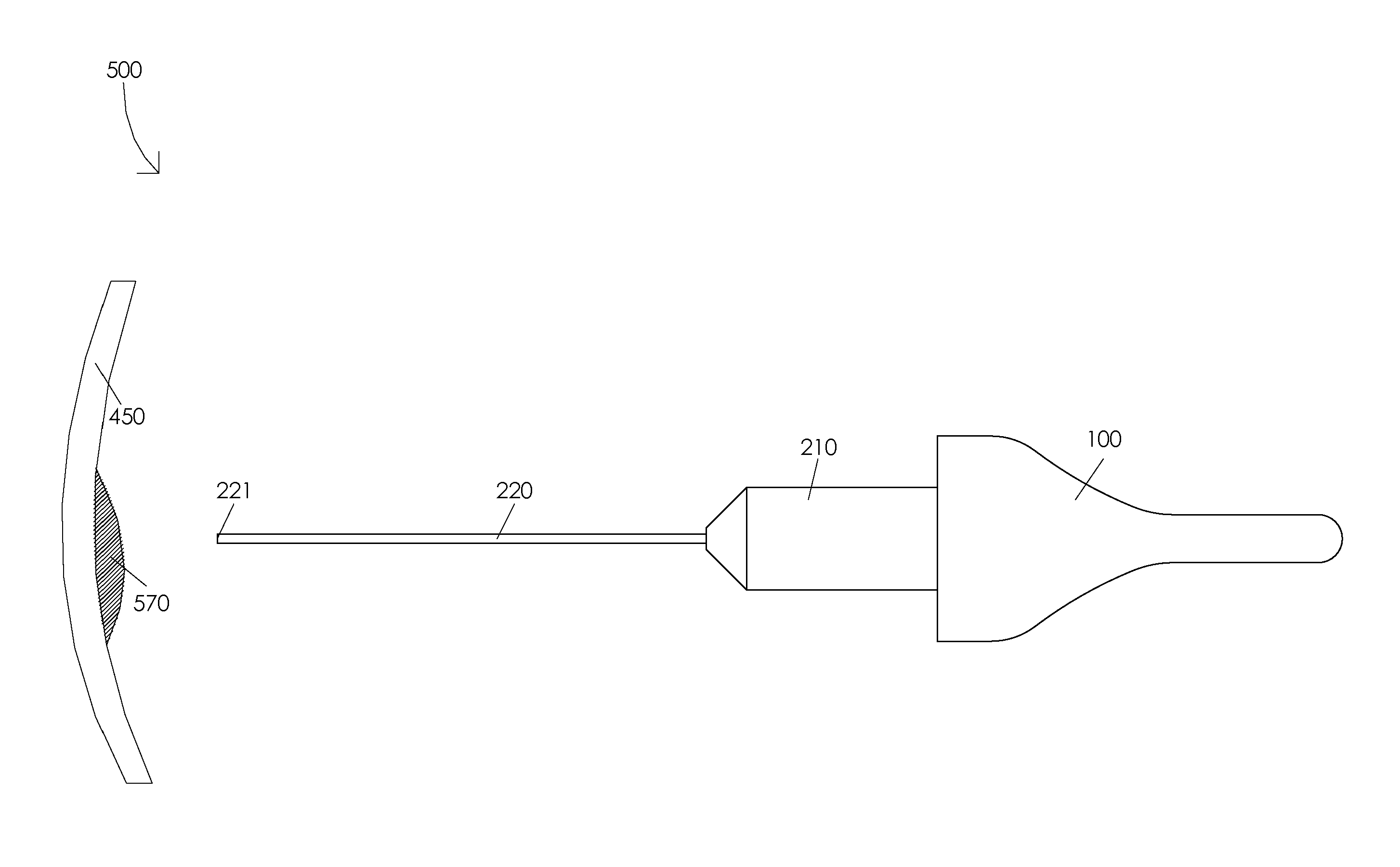
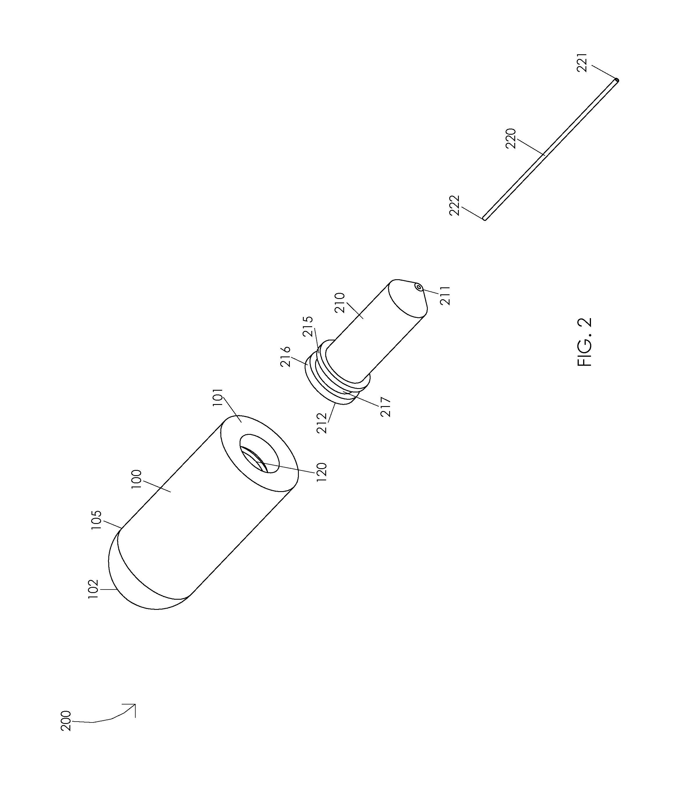
The present invention is about a membrane visualization instrument. It consists of a flow control mechanism, a visualization fluid chamber, a visualization fluid guide, and a hypodermic tube. The visualization fluid guide is located within the flow control mechanism and the hypodermic tube is located within the visualization fluid guide. The instrument allows for the visualization of membranes using a visualization fluid. The compression and decompression of the flow control mechanism controls the delivery and absorption of the visualization fluid. The technical effects of this invention include improved visualization of membranes and more efficient delivery of dye for visualization.

Problems solved by technology

Removing the internal limiting membrane is difficult because the internal limiting membrane is transparent and invisible under a microscope.
Unfortunately, epiretinal membranes are often transparent and difficult to identify.
For example, it may be difficult for a surgeon to visualize all or a portion of an epiretinal membrane.

Method used


Image

  • Membrane visualization instrument
  • Membrane visualization instrument
  • Membrane visualization instrument

Examples


Embodiment Construction

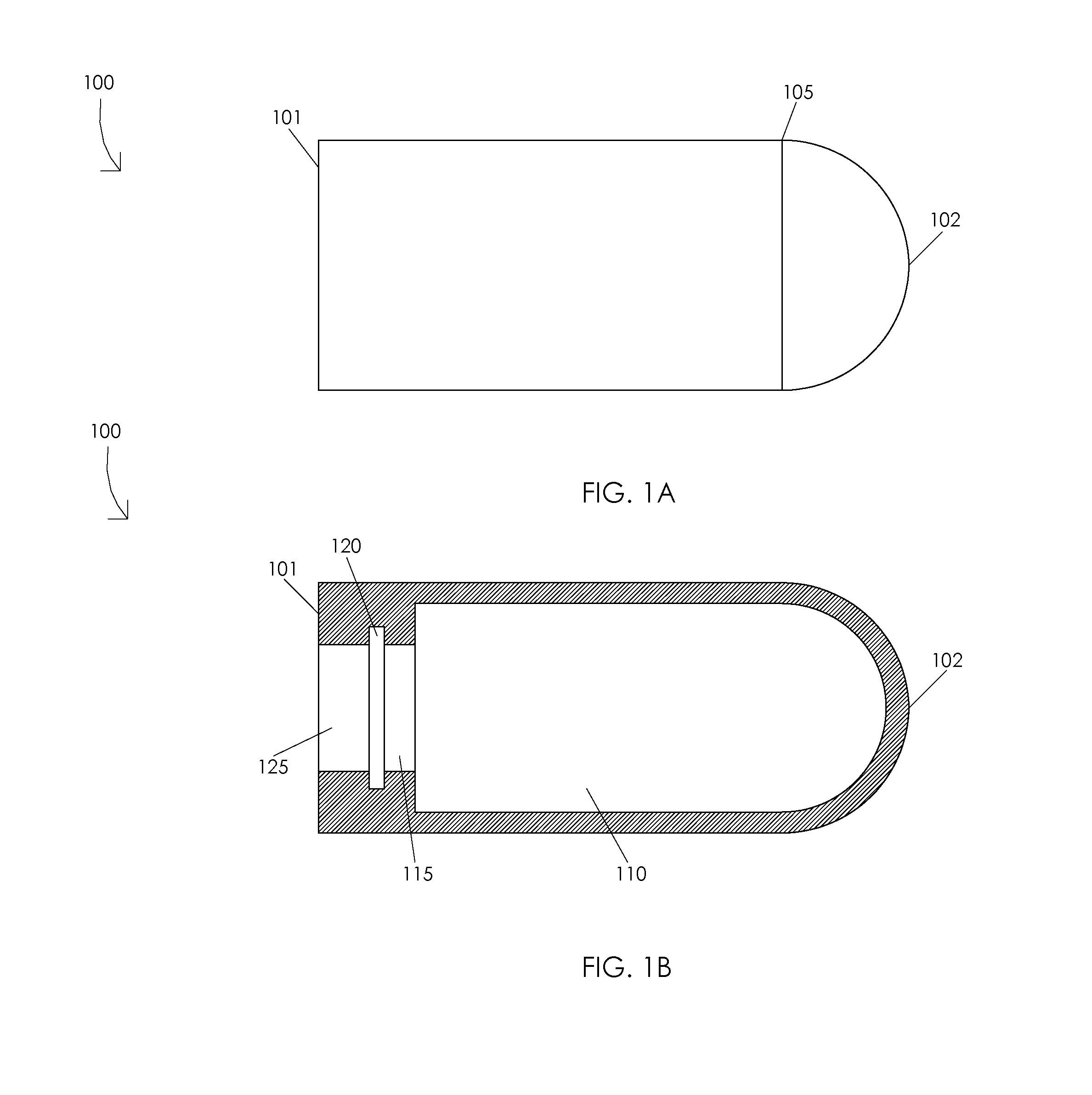
[0020]FIGS. 1A and 1B are schematic diagrams illustrating a flow control mechanism 100. FIG. 1A illustrates a top view of a flow control mechanism 100. Illustratively, flow control mechanism 100 may comprise a flow control mechanism distal end 101, a flow control mechanism proximal end 102, and a flow control mechanism dome interface 105. In one or more embodiments, flow control mechanism 100 may be manufactured from any suitable material, e.g., polymers, metals, metal alloys, etc., or from any combination of suitable materials.

[0021]FIG. 1B illustrates a cross-sectional view of a flow control mechanism 100. Illustratively, flow control mechanism 100 may comprise a visualization fluid chamber 110, a locking depression housing 115, a distal locking lip housing 120, and a visualization fluid guide housing 125. In one or more embodiments, flow control mechanism 100 may have a density in a range of 0.02 to 0.06 pounds per cubic inch, e.g., flow control mechanism 100 may have a density o...


PUM


Abstract

A membrane visualization instrument may include a flow control mechanism having a flow control mechanism distal end and a flow control mechanism proximal end, a visualization fluid chamber of the flow control mechanism, a visualization fluid guide having a visualization fluid guide distal end and a visualization fluid guide proximal end, and a hypodermic tube having a hypodermic tube distal end and a hypodermic tube proximal end. The visualization fluid guide proximal end may be disposed within the flow control mechanism. The hypodermic tube proximal end may be disposed within the visualization fluid guide. A visualization fluid, e.g., indocyanine green dye, kenalog, trypan blue dye, etc., may be disposed within the visualization fluid chamber. A compression of the flow control mechanism may be configured to irrigate the visualization fluid out of the hypodermic tube proximal end.

Description

CROSS-REFERENCE TO RELATED APPLICATIONS[0001]This application claims the benefit of U.S. Provisional Application No. 61 / 736,378, filed Dec. 12, 2012.FIELD OF THE INVENTION[0002]The present disclosure relates to a medical device, and, more particularly, to a surgical instrument.BACKGROUND OF THE INVENTION[0003]Some ophthalmic surgical procedures require identification and removal of membranes. An internal limiting membrane is the structural interface between the retina and the vitreous. Ophthalmic surgeons remove the internal limiting membrane to treat a variety of retinal disorders, e.g., macular hole, epiretinal membrane, diabetic macular edema, retinal vein occlusion, etc. The removal of the internal limiting membrane is typically accomplished by incising and peeling the internal limiting membrane from the retina. Removing the internal limiting membrane is difficult because the internal limiting membrane is transparent and invisible under a microscope. Accordingly, there is a need...

Claims


Application Information

Patent Timeline
IPC IPC(8): A61B3/10A61F9/007
CPCA61F9/00736A61B3/10
Inventor SCHELLER, GREGG D.HOLEKAMP, NANCY M.
Owner KATALYST SURGICAL
Learn More