Method for regulating the torque of a control surface actuator with a controlled angular position on an aircraft with mechanical flight control

a technology of mechanical flight control and actuator, which is applied in the direction of vehicle position/course/altitude control, process and machine control, instruments, etc., can solve the problems of actuator disengagement, solution does not take into account the increase in actuator torqu

Active Publication Date: 2014-06-12
THALES SA
View PDF24 Cites 10 Cited by
  • Summary
  • Abstract
  • Description
  • Claims
  • Application Information

AI Technical Summary

Benefits of technology

[0017]The regulation of the speed of movement of the control surface makes it possible to avoid reaching torque values greater than the critical value beyond which there is a risk of disengaging the actuator.
[0019]For a given angular position, the regulation of the maximum speed of movement of the control surface makes it possible to avoid excessively rapid changes in the torque exerted on the control surface, which makes it possible to avoid exceeding the threshold torque value.
[0020]According to one variant of the invention, a method is proposed as described previously in which the maximum speed of movement of the control surface decreases when the torque exerted on the control surface by the external forces increases.
[0023]According to one variant of the invention, a method is proposed as described previously in which the second step moreover comprises a step consisting in reducing the measurement noise for the torque exerted by the external forces on the control surface.

Problems solved by technology

This first solution presents a drawback, since the autopilot disengages, which gives rise to violent changes of trajectory which are unpleasant for the passengers and potentially dangerous when the aircraft is at low altitude.
Disengagement of the actuator when the control surface arrives at a limit stop constitutes another drawback.
However, this solution does not take into account increases in the torque exerted by the actuator to compensate for the increases in the torque exerted on the control surface by the external forces for a constant position.
For example, this solution does not take into account large increases in torque exerted on the control surface in the event of an engine failure or violent gusts of wind.

Method used


Image

  • Method for regulating the torque of a control surface actuator with a controlled angular position on an aircraft with mechanical flight control
  • Method for regulating the torque of a control surface actuator with a controlled angular position on an aircraft with mechanical flight control
  • Method for regulating the torque of a control surface actuator with a controlled angular position on an aircraft with mechanical flight control

Examples


Embodiment Construction

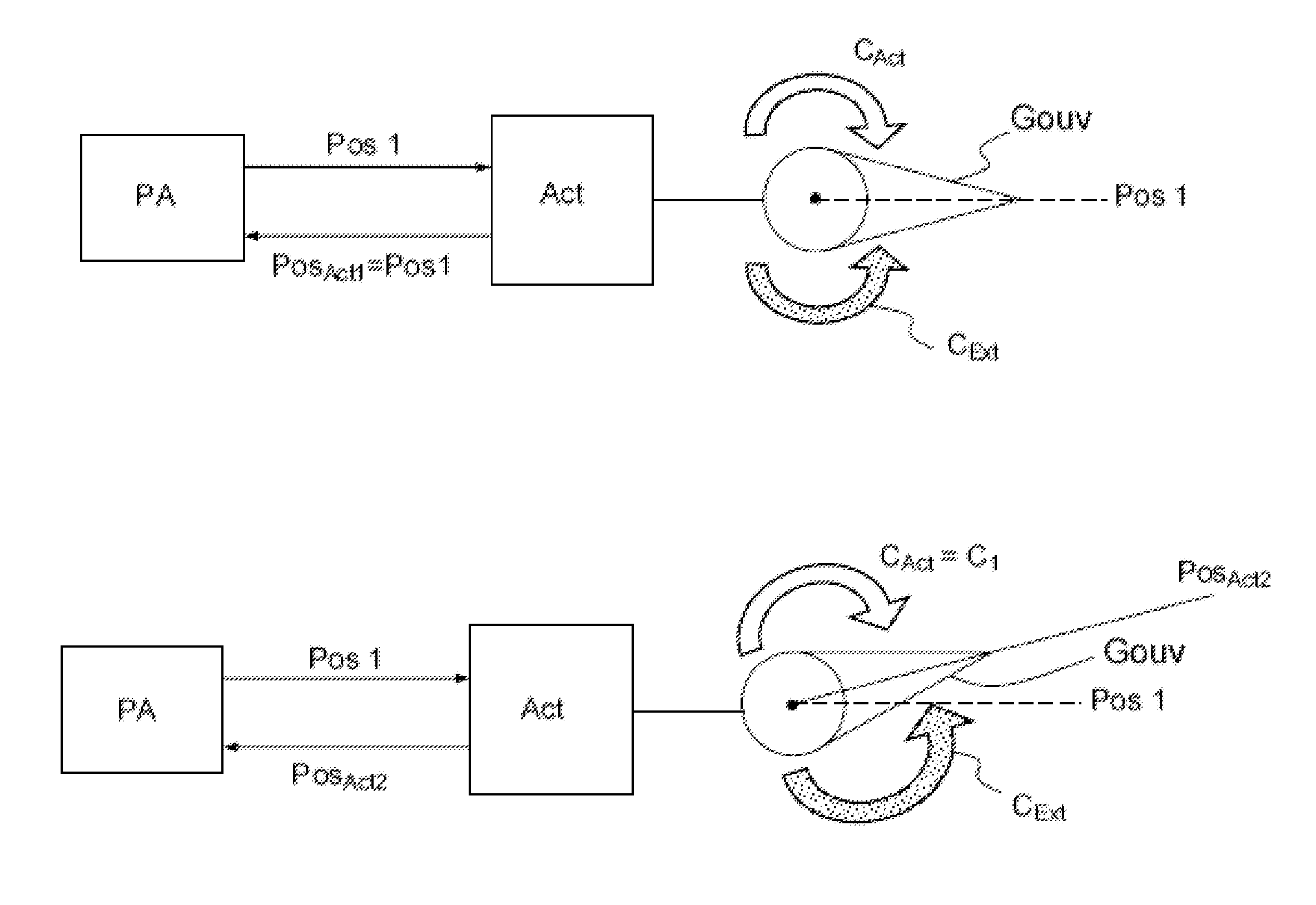
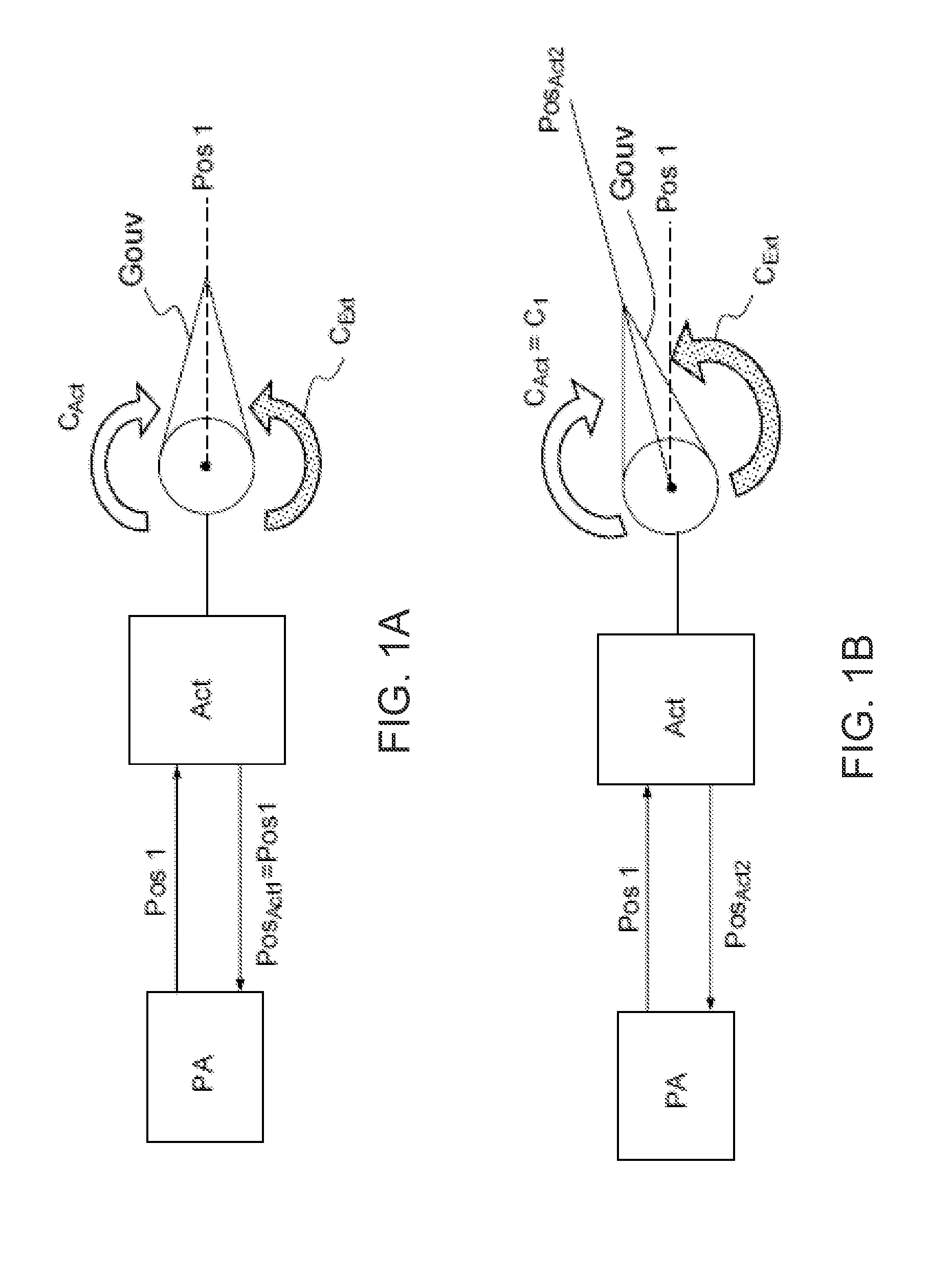
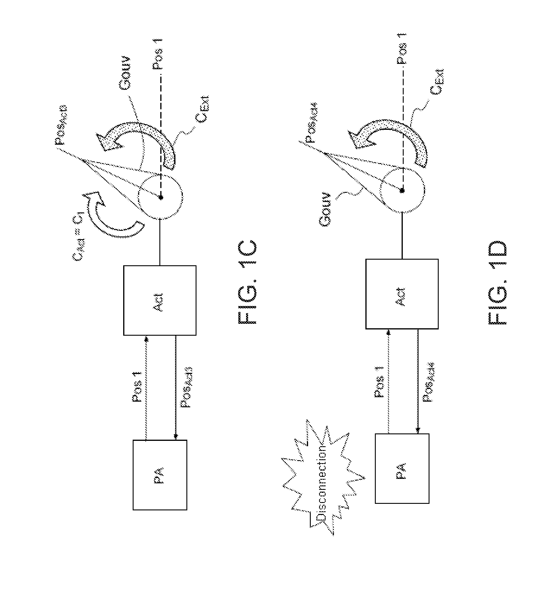
[0030]FIG. 1 show the operating principle of a control surface actuator regulated in terms of position on an aircraft with mechanical flight control.

[0031]FIG. 1A illustrates an autopilot module PA, an actuator Act comprising a position control loop and a control surface Gouv. The autopilot module PA orders a first setpoint angular position Pos1 for the actuator, making it possible to follow a direction of the aircraft. The control surface Gouv is then moved by the actuator Act. In this case, the first setpoint angular position Pos1 corresponds to a nominal position of the control surface Gouv, defined previously, i.e. during configuration of the autopilot module PA.

[0032]A torque CExt, represented by a shaded arrow, is exerted on the control surface Gouv by external forces. The external forces are generally aerodynamic forces. A torque CAct, represented by a white arrow, exerted by the actuator Act compensates for the torque due to the external forces, which makes it possible to ma...


PUM


Abstract

A method for regulating an actuator for a control surface is provided, which actuator has an angular position controlled by an autopilot on an aircraft with mechanical flight control. When the value of the torque exerted by the actuator is less than a threshold torque value, the actuator is regulated in terms of position and the maximum speed of movement of the control surface is limited to a value that is dependent on the torque value. When the value of the torque exerted by the actuator is greater than the threshold torque value, the actuator is regulated in terms of torque.

Description

CROSS-REFERENCE TO RELATED APPLICATION[0001]This application claims priority to foreign French patent application No. FR 1202129, filed on Jul. 27, 2012, the disclosure of which is incorporated by reference in its entirety.FIELD OF THE INVENTION[0002]The field of the invention concerns the regulation of a control surface actuator, said control surface being controlled by the autopilot of an aircraft with mechanical flight control.BACKGROUND[0003]Flight controls are systems linking the pilot or autopilot module and the control surfaces that allow the trajectory of the aircraft to be modified. Flight controls notably comprise a steering element such as a joystick and a mechanical system for actuating the control surfaces. In this case, the mechanical system comprises an actuator, the actuator being an electric motor of rotary type generating a torque which compensates for the torque exerted on the control surface by external forces of aerodynamic type.[0004]The certification authoriti...

Claims


Application Information

Patent Timeline
Patent Type & Authority Applications(United States)
IPC IPC(8): B64C13/18
CPCB64C13/18G05D1/0066
Inventor PIERRE, ROMAINBONNAFFOUX, ARNAUDADAMSKI, CAROLINE
Owner THALES SA
Why Eureka
Try Eureka