
Image processing apparatus and image processing method

Active Publication Date: 2014-06-19
CANON KK
View PDF7 Cites 5 Cited by
  • Summary
  • Abstract
  • Description
  • Claims
  • Application Information

AI Technical Summary

Benefits of technology

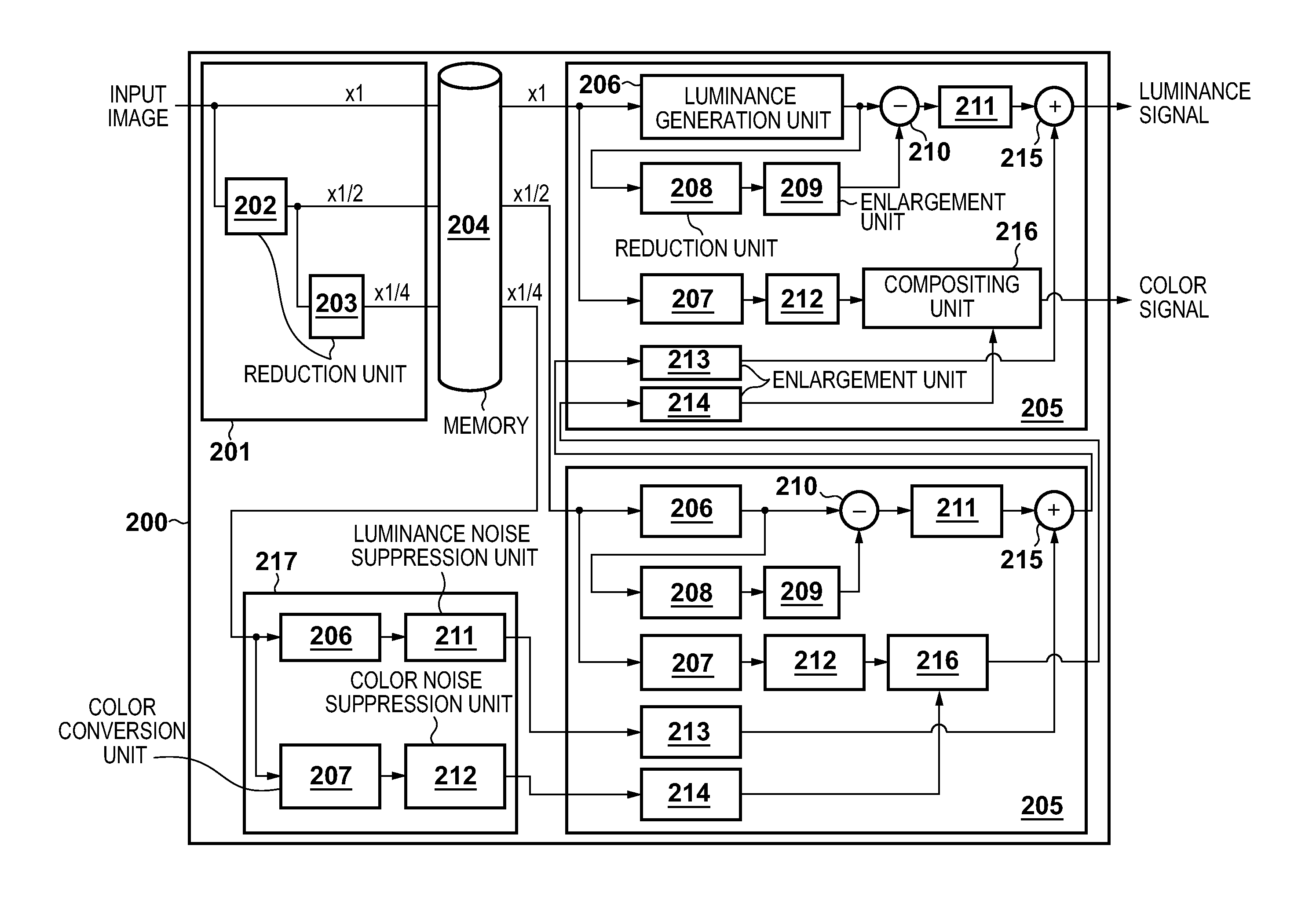
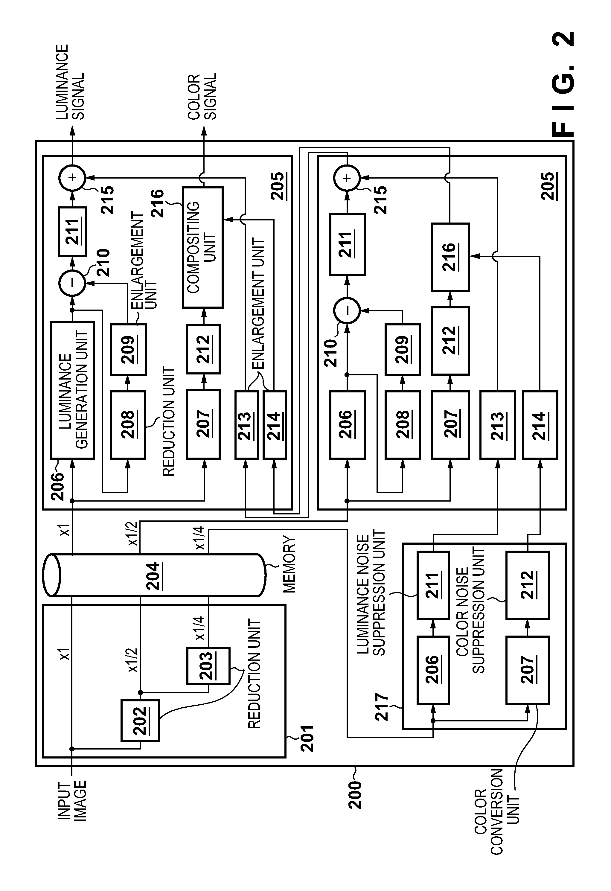
The invention aims to improve image processing by separating images into different frequency bands and then recombining them to reduce noise. This technique helps to suppress noise without compromising image quality.

Problems solved by technology

In recent years, image signals obtained from an image sensor contain more noise components due to a decrease in the size of pixels.
On the other hand, as all of the separated images are composited, noise that remains in the band-separated images even after noise suppression remains in the recomposited image.
In particular, if high-frequency color noise, which is visually unpleasant, remains in the recomposited image, the color noise causes deterioration in the image quality of the recomposited image.
The method disclosed in Japanese Patent Laid-Open No. 2009-199104 has the problem that a reduction in the detection accuracy for edge signals leads to the occurrence of compositing unevenness in edge portions of the recomposited image.
As described above, according to the method in which an image is separated into a plurality of bands with no overlapping by using the Laplacian pyramid and the like, noise is suppressed in each separated image, and then the separated images are recomposited, compositing unevenness does not easily occur as the compositing ratio is not calculated, but the noise suppression effect is difficult to improve because images of all bands are recomposited.

Method used


Image

  • Image processing apparatus and image processing method
  • Image processing apparatus and image processing method
  • Image processing apparatus and image processing method

Examples


first embodiment

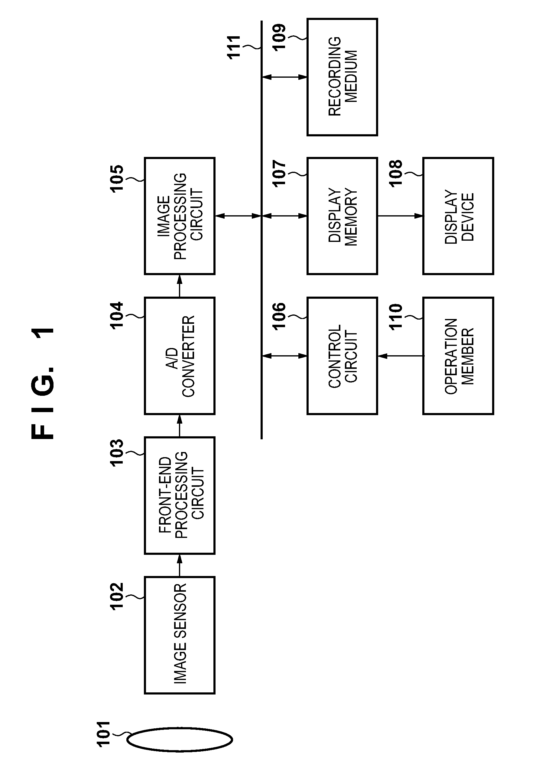
[0026]FIG. 1 is a block diagram showing an example of a functional configuration of a digital camera, which is one example of application of an image processing apparatus according to embodiments of the present invention. It should be noted that the image processing apparatus of the present invention is not limited to being applied to a digital camera, and may also be applied to a digital video camera, a computer (notebook, desktop, tablet, etc.), and any other electronic devices capable of executing image processing. Examples of such electronic devices include mobile information terminals (PDA), telephones, game consoles, media players, navigation systems, appliances, and vehicles.

[0027]Referring to FIG. 1, an optical system 101, which is illustrated as one lens for convenience, includes a lens group composed of a zoom lens and a focus lens, a diaphragm, and a shutter. This optical system 101 adjusts a scale factor for an image of a subject formed on an imaging surface of an image ...

second embodiment

[0060]A description is now given of a second embodiment of the present invention. It is sufficient for an overall configuration of the present embodiment to be the same as that of the first embodiment, and therefore a description of common parts is omitted from the following description. The present embodiment differs from the first embodiment in a band dividing method used in noise suppression for luminance signals, that is to say, a configuration of noise suppression units.

[0061]FIG. 5 is a block diagram showing an example of a functional configuration of a noise suppression unit 300 included in an image processing circuit 105 of a digital camera according to the present embodiment, and constituent elements that are the same as those shown in FIG. 2 are given the same reference signs thereas. In the first embodiment, noise suppression for band images other than the lowest-band images is performed using the middle and upper layer processing units 205 that are configured basically i...


PUM


Abstract

An input image is divided into images composed of luminance signals of a plurality of bands that make up the Laplacian pyramid, noise suppression is applied to each divided image, and then the divided images are composited by addition. The input image is also divided into images composed of color signals of a plurality of bands that make up the Gaussian pyramid, noise suppression is applied to each divided image, and the divided images are composited at an image-based ratio. By thus compositing the luminance signals and color signals, excellent noise suppression can be realized while alleviating deterioration in the image quality during the compositing.

Description

BACKGROUND OF THE INVENTION[0001]1. Field of the Invention[0002]The present invention relates to an image processing apparatus and an image processing method, and in particular to an image processing apparatus and an image processing method that can suppress noise in images.[0003]2. Description of the Related Art[0004]In recent years, image signals obtained from an image sensor contain more noise components due to a decrease in the size of pixels. A method is known for suppressing noise components contained in image signals by using multi-rate signal processing.[0005]Japanese Patent Laid-Open No. 2008-293425 discloses a method in which image signals are separated into a plurality of frequency components using techniques such as the wavelet transform and the Laplacian pyramid, noise is suppressed for each frequency component, and then the frequency components are recomposited. For example, when the Laplacian pyramid is used, a low-band image is obtained by applying reduction processi...

Claims


Application Information

Patent Timeline
IPC IPC(8): G06T5/00H04N9/64G06T7/00
CPCH04N9/77G06T2207/20016H04N9/646G06T5/70
Inventor HIRAI, SHINYA
Owner CANON KK
Learn More