Touch sensor integrated type display device

a display device and touch sensor technology, applied in the field of touch sensor integrated type display devices, can solve the problems of user dissatisfaction, reduced visibility of display devices, increased thickness of display devices, etc., to prevent a reduction in touch sensitivity, reduce mutual capacitance, and increase parasitic capacitance

Active Publication Date: 2014-06-19
LG DISPLAY CO LTD
View PDF2 Cites 51 Cited by
  • Summary
  • Abstract
  • Description
  • Claims
  • Application Information

AI Technical Summary

Benefits of technology

[0025]As described above, the touch sensor integrated type display device according to the embodiments of the invention can reduce the number of touch driving electrodes or the number of touch sensing electrodes used as the touch effective electrode by connecting the touch non-driving electrodes to the touch sensing electrode or by connecting the touch non-sensing electrodes to the touch driving electrode. Hence, the touch sensor integrated type display device according to the embodiments of the invention can reduce the mutual capacitance between the touch driving electrodes and the touch sensing electrodes, thereby making it possible to prevent a reduction in the touch sensitivity and an increase in the parasitic capacitance and further improve a touch performance.
[0026]Furthermore, the touch sensor integrated type display device according to the embodiments of the invention can use the common electrode, which is used to form an electric field required to drive liquid crystals of the display device, along with the pixel electrode as the touch driving electrode or the touch sensing electrode, thereby making it possible to omit a process for forming the touch driving electrode or the touch sensing electrode and reduce a thickness of the touch sensor integrated type display device by a thickness of the touch driving electrode or the touch sensing electrode.

Problems solved by technology

However, when the user makes use of these input devices, user's dissatisfaction increases because the user is required to know how to use the input devices and the input devices occupy space.
There is a problem that a thickness of the display device increases because the add-on type touch sensor has the structure in which the add-on type touch sensor is mounted on the display device.
Further, the visibility of the display device is reduced because of a reduction in brightness of the display device due to the increased thickness.

Method used


Image

  • Touch sensor integrated type display device
  • Touch sensor integrated type display device
  • Touch sensor integrated type display device

Examples


first embodiment

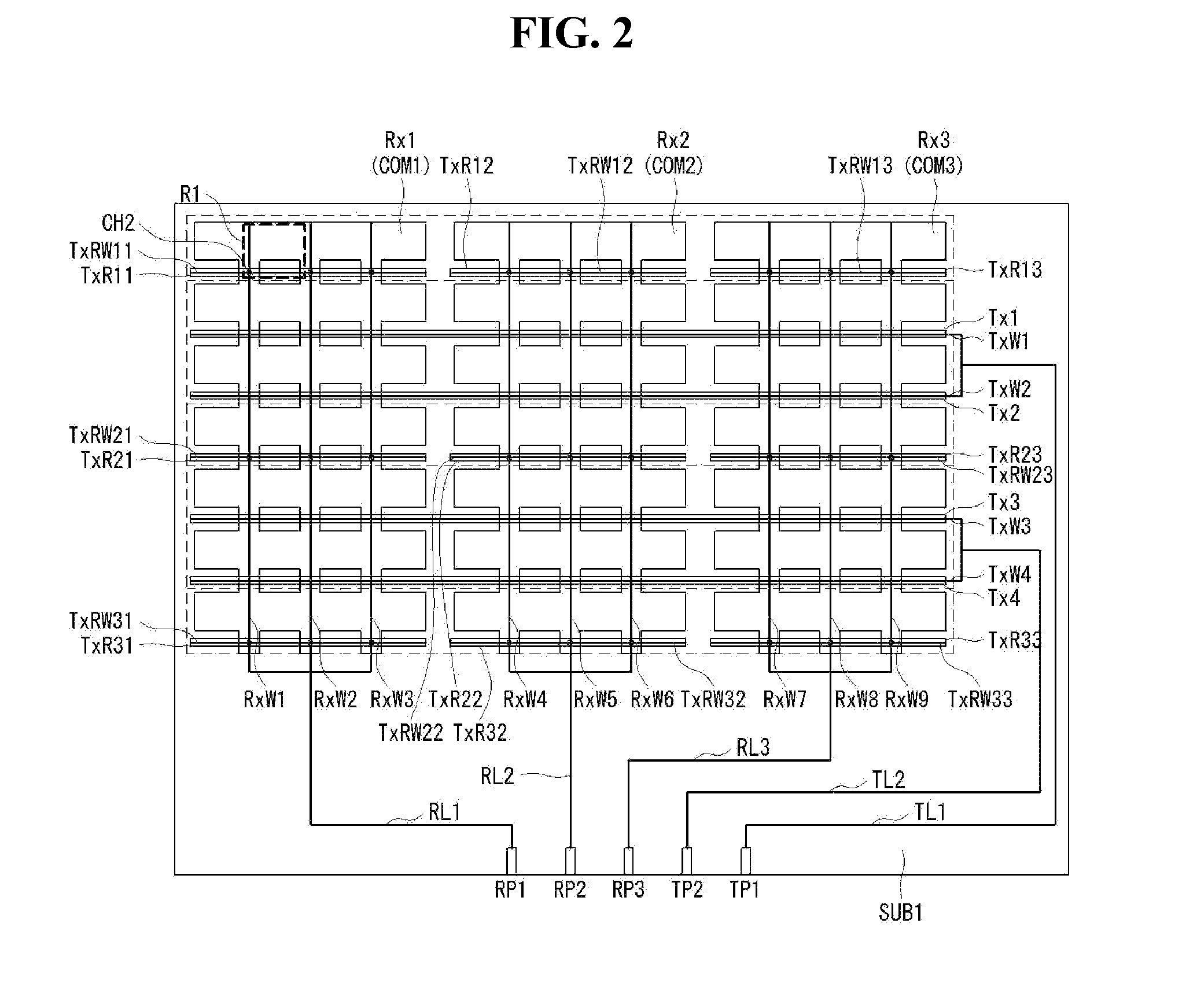
[0043]Referring to FIGS. 2 and 3, the common electrode according to the invention is divided into the plurality of common electrodes and serves as a touch sensing electrode. Thus, in the following description, the common electrode is referred to as the common electrode serving as the touch sensing electrode, the touch sensing electrode, or the touch sensing electrode serving as the common electrode, if necessary or desired.

[0044]As shown in FIG. 2, the common electrodes include a plurality of first to third common electrodes COM1 to COM3 divided in the second direction (for example, y-axis direction). Each of the first to third common electrodes COM1 to COM3 is configured so that a plurality of electrode patterns having a predetermined shape are connected to one another by connection portions and form electrode lines in the y-axis direction. In the first embodiment of the invention, the electrode patterns have a rectangular shape as an example, but may have other shapes. The first t...

second embodiment

[0067]Referring to FIGS. 6 and 7, a common electrode according to the invention is divided into a plurality of common electrodes and serves as a touch driving electrode. Thus, in the following description, the common electrode is referred to as the common electrode serving as the touch driving electrode, the touch driving electrode, or the touch driving electrode serving as the common electrode, if necessary or desired.

[0068]As shown in FIG. 6, the common electrodes include a plurality of first to third common electrodes COM1 to COM3 divided in a second direction (for example, y-axis direction). Each of the first to third common electrodes COM1 to COM3 is configured so that a plurality of electrode patterns having a predetermined shape are connected to one another by connection portions and form electrode lines in the y-axis direction. In the second embodiment of the invention, the electrode patterns have a rectangular shape as an example, but may have other shapes. The first to thi...


PUM


Abstract

A touch sensor integrated type display device includes gate lines and data lines; a plurality of pixel electrodes respectively formed in pixel areas defined by crossings of the gate and data lines; a first electrode formed between first pixel electrodes and in parallel with a first gate line of the gate lines, the first pixel electrodes being adjacent to each other with the first gate line interposed therebetween; second electrodes formed between second pixel electrodes and arranged in a line in parallel with a second gate line adjacent to the first gate line, the second pixel electrodes being adjacent to each other with the second gate line interposed therebetween; and third electrodes, each of which is formed in parallel with the data lines and contacts the second electrodes, at least a portion of each of the third electrodes overlapping the first and second pixel electrodes.

Description

[0001]This application claims the benefit of priority under 35 U.S.C. §119(a) to Korea Patent Application No. 10-2012-0145339 filed on Dec. 13, 2012, the entire contents of which is incorporated herein by reference herein in its entirety.BACKGROUND OF THE INVENTION[0002]1. Field of the Invention[0003]Embodiments of the invention relate to a touch sensor integrated type display device capable of recognizing a user's touch operation.[0004]2. Discussion of the Related Art[0005]In recent years, various input devices such as a keyboard, a mouse, a joystick, and a digitizer have been used to construct interfaces between users and home appliances or information telecommunication devices. However, when the user makes use of these input devices, user's dissatisfaction increases because the user is required to know how to use the input devices and the input devices occupy space. Therefore, a convenient and simple input device that can reduce erroneous operation is required. In response to thi...

Claims


Application Information

Patent Timeline
Patent Type & Authority Applications(United States)
IPC IPC(8): G06F3/041
CPCG06F3/041G02F1/13338G02F1/136204G06F3/0412G06F3/0446G02F1/134372G06F3/044G06F2203/04106G06F3/0445
Inventor HAN, MANHYEOPKIM, JINSEONG
Owner LG DISPLAY CO LTD
Why Eureka
Try Eureka