
Rotary mechanism and related electronic device

a technology of electronic devices and rotating mechanisms, which is applied in the direction of instruments, portable computer details, and electric apparatus casings/cabinets/drawers, etc., can solve the problems of reducing convenience in operation, complicated structure limited rotation range of conventional rotary mechanisms, so as to maintain the stability of electronic devices, simple structure, and easy operation

Active Publication Date: 2014-06-19
WISTRON CORP
View PDF17 Cites 20 Cited by
  • Summary
  • Abstract
  • Description
  • Claims
  • Application Information

AI Technical Summary

Benefits of technology

The present invention provides a rotary mechanism with a simple structure that allows for a large angle of rotation. This mechanism allows for stable positioning of the screen when placed on a supporting surface, while still providing protection for the device. The mechanism also allows for easy adjustment of the distance between the supporting component and the shaft during rotation to prevent interference between parts. The electronic device utilizing this mechanism can fold and unfold stably, and the angle between the casings can be adjusted to specific angles for convenient switching between operation modes.

Problems solved by technology

Since operation of the touch panel does not meet a user's needs, a portable computer device combining a notebook computer host with keyboard and the touch panel arises for solving above drawbacks.
Structure of the conventional rotary mechanism is complicated, and rotation range of the conventional rotary mechanism is limited.
As a result, it reduces convenience in operation.

Method used


Image

  • Rotary mechanism and related electronic device
  • Rotary mechanism and related electronic device
  • Rotary mechanism and related electronic device

Examples


Embodiment Construction

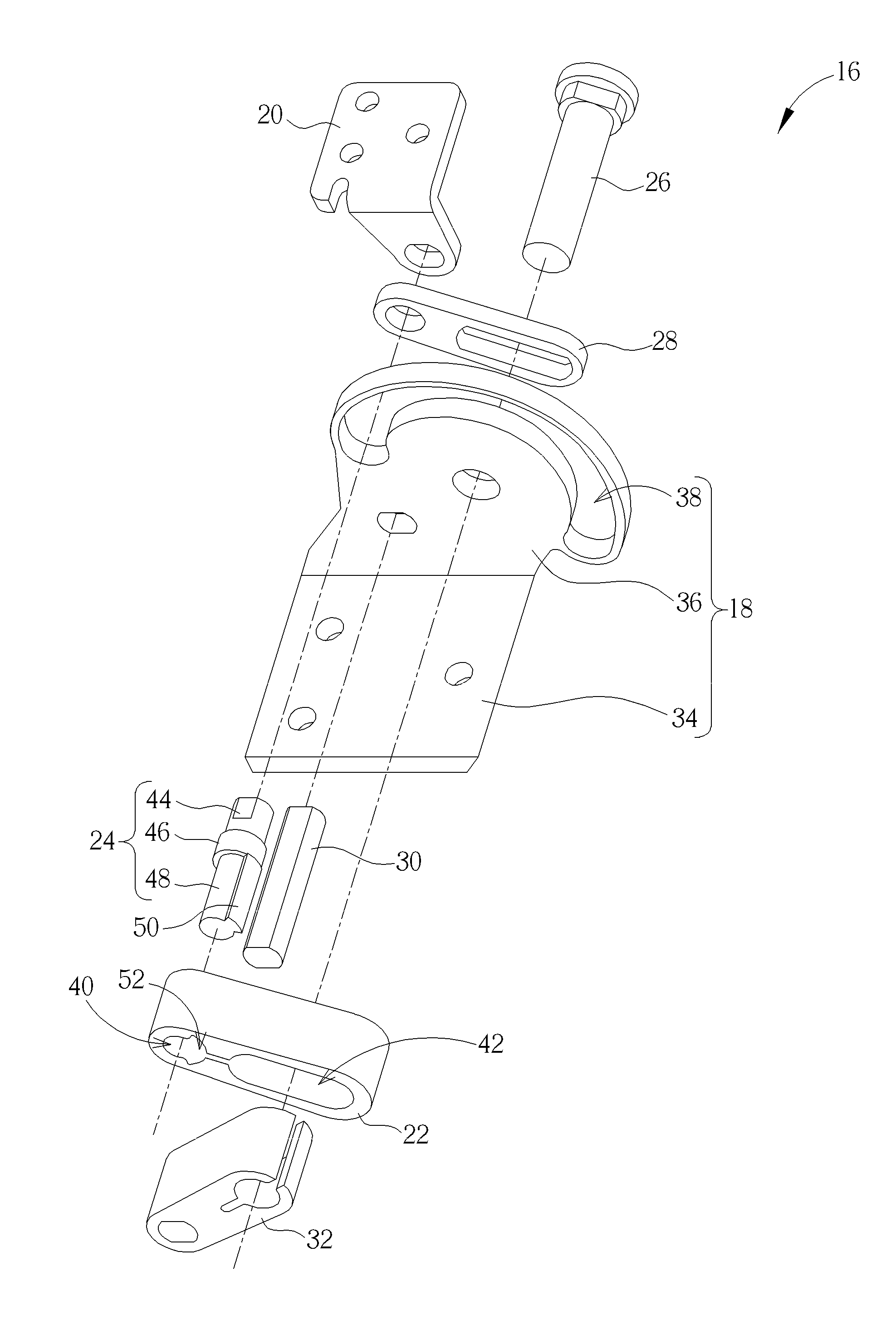
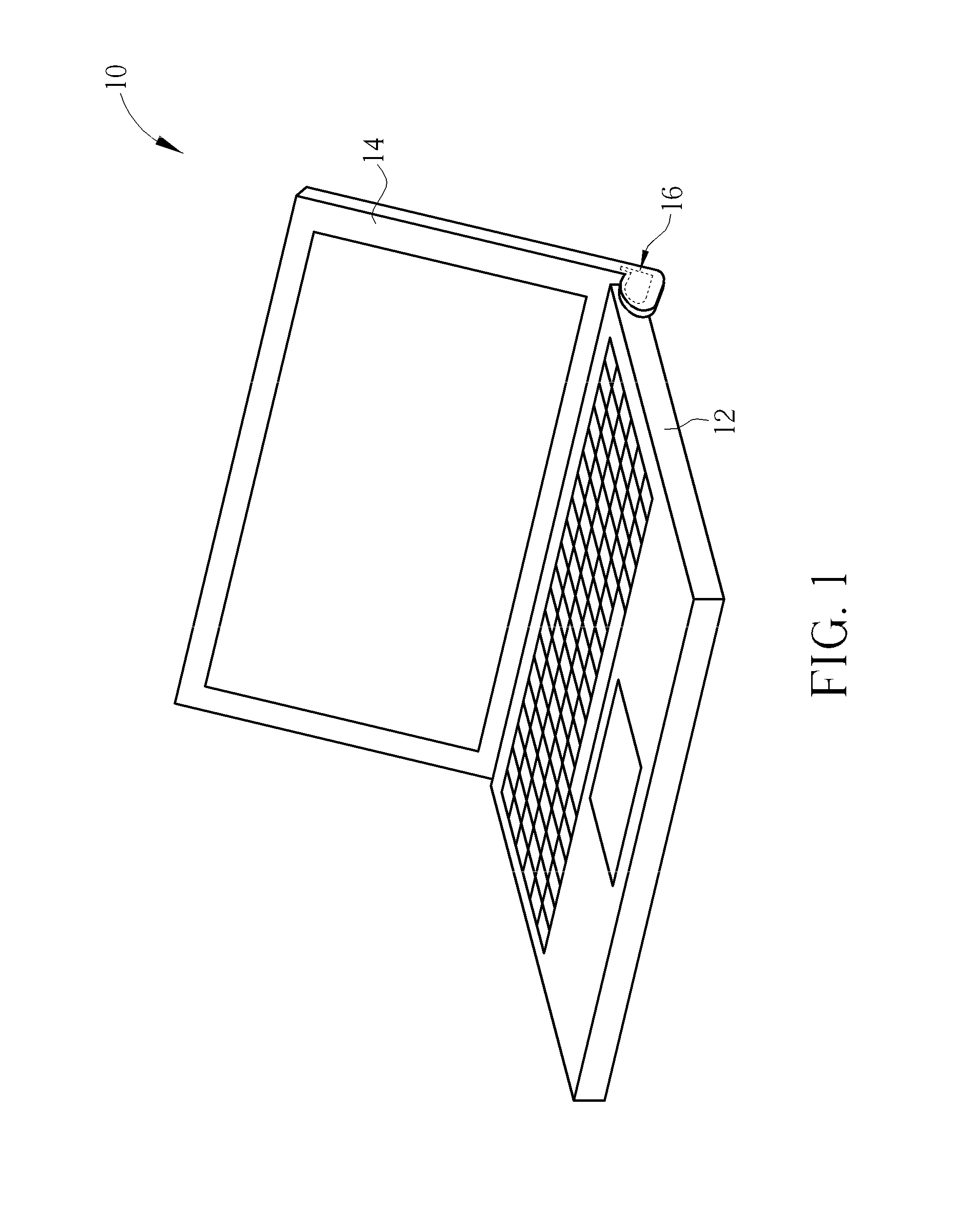
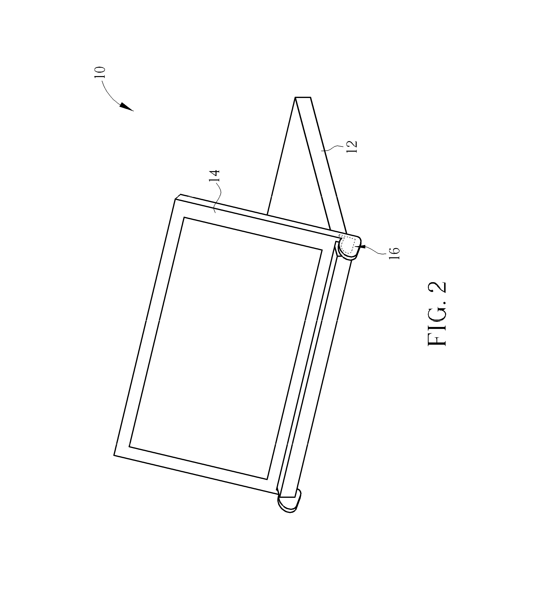
[0029]Please refer to FIG. 1 and FIG. 2. FIG. 1 and FIG. 2 respectively are diagrams of an electronic device 10 in different operation modes according to an embodiment of the present invention. The electronic device 10 includes a first casing 12, a second casing 14 and a rotary mechanism 16. The electronic device 10 can be a notebook computer, the first casing 12 can be a host, the second casing 14 can be a screen, and the rotary mechanism 16 is disposed between the first casing 12 and the second casing 14. The second casing 14 can be the touch screen pivoting to the first casing 12 via the rotary mechanism 16.

[0030]In the operation mode shown in FIG. 1, an included angle between the first casing 12 and the second casing 14 can be smaller than 180 degrees. In the meantime the keyboard on the host (the first casing 12) faces upward, and the electronic device 10 can be the notebook computer mode. In the other operation mode shown in FIG. 2, the included angle between the first casing ...


PUM


Abstract

A rotary mechanism includes a base, a supporting component, a bridging component, a guiding component and a shaft. The base includes a guiding structure. The guiding structure includes a first area, a curvature of the first area is increased from a front end to a rear end of the first area. The bridging component includes a pivot hole and a guiding slot. The guiding component passes through the base and is movably disposed inside the guiding structure. Two ends of the guiding component are respectively disposed on the supporting component and the pivot hole, and the supporting component can rotate relative to the bridging component via the guiding component. The shaft passes through the base and is movably disposed inside the guiding slot. The guiding component moves along the guiding structure, and the supporting component can rotate relative to the base via the bridging component and the shaft.

Description

BACKGROUND OF THE INVENTION[0001]1. Field of the Invention[0002]The present invention relates to a rotary mechanism and a related electronic device, and more particularly, to a rotary mechanism with simple structure and large rotation range and a related electronic device.[0003]2. Description of the Prior Art[0004]A conventional tablet computer utilizes a touch panel to perform touch control instruction. Since operation of the touch panel does not meet a user's needs, a portable computer device combining a notebook computer host with keyboard and the touch panel arises for solving above drawbacks. Conventionally, a host module cooperatively with a hinge mechanism pivoted to the host module are utilized for supporting the touch panel, and a track is utilized for sliding the touch panel relative to the host module. For convenient operation, the rotatable touch panel is applied to the conventional notebook computer, and the related rotary mechanism includes the shaft-type mechanism and...

Claims


Application Information

Patent Timeline
Patent Type & Authority Applications(United States)
IPC IPC(8): G06F1/16
CPCG06F1/1618G06F1/1681
Inventor JHENG, SHAN-WEI
Owner WISTRON CORP
Learn More