Needle Retraction Apparatus

a needle retraction and needle technology, applied in the field of needle retraction apparatus, can solve the problems of exposing the user to the risk of needle-stick injury, and achieve the effect of preventing the exposure of contaminated needles or bodily fluids

Active Publication Date: 2014-06-19
RETRACTABLE TECH INC
View PDF17 Cites 17 Cited by
  • Summary
  • Abstract
  • Description
  • Claims
  • Application Information

AI Technical Summary

Benefits of technology

[0015]A needle retraction apparatus as disclosed herein desirably comprises a retraction chamber that is external to the syringe or plunger handle and has sufficient retraction force to retract a needle that is still inserted into a patient's body, thereby preventing exposure of the contaminated needle or bodily fluids carried on or in the needle to others. Where the needle retraction apparatus is used with a syringe, a clinician administering an injection desirably rotates the syringe barrel in either direction relative to the body of the apparatus. As the body of the apparatus is stabilized by one hand of the user, the syringe barrel is rotated relative to the body, which first causes the slide member to move laterally out of coaxial alignment with the needle holder and needle, and then to move the retraction chamber into substantial coaxial alignment with the head of the needle holder, allowing the needle holder to carry the attached needle rearwardly to a fully retracted position where the needle is released from the patient and the needle tip no longer projects forwardly from the body of the attachment device.

Problems solved by technology

The only known syringe having a changeable, retractable needle does not have a conventional luer lock connection, and the retraction mechanism is activated by the application of a forwardly directed force to the plunger handle following removal of the needle from a patient, thereby exposing the needle and also exposing the user to the risk of needle-stick injury.

Method used


Image

  • Needle Retraction Apparatus
  • Needle Retraction Apparatus
  • Needle Retraction Apparatus

Examples


Embodiment Construction

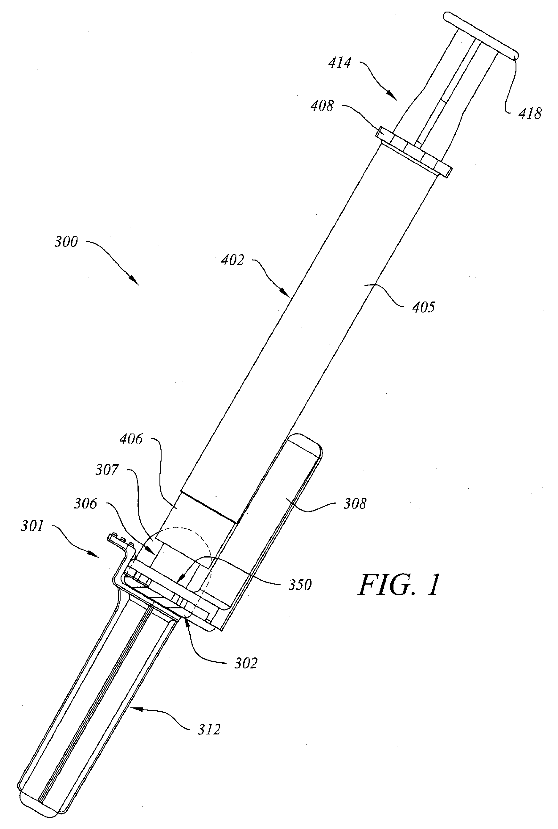
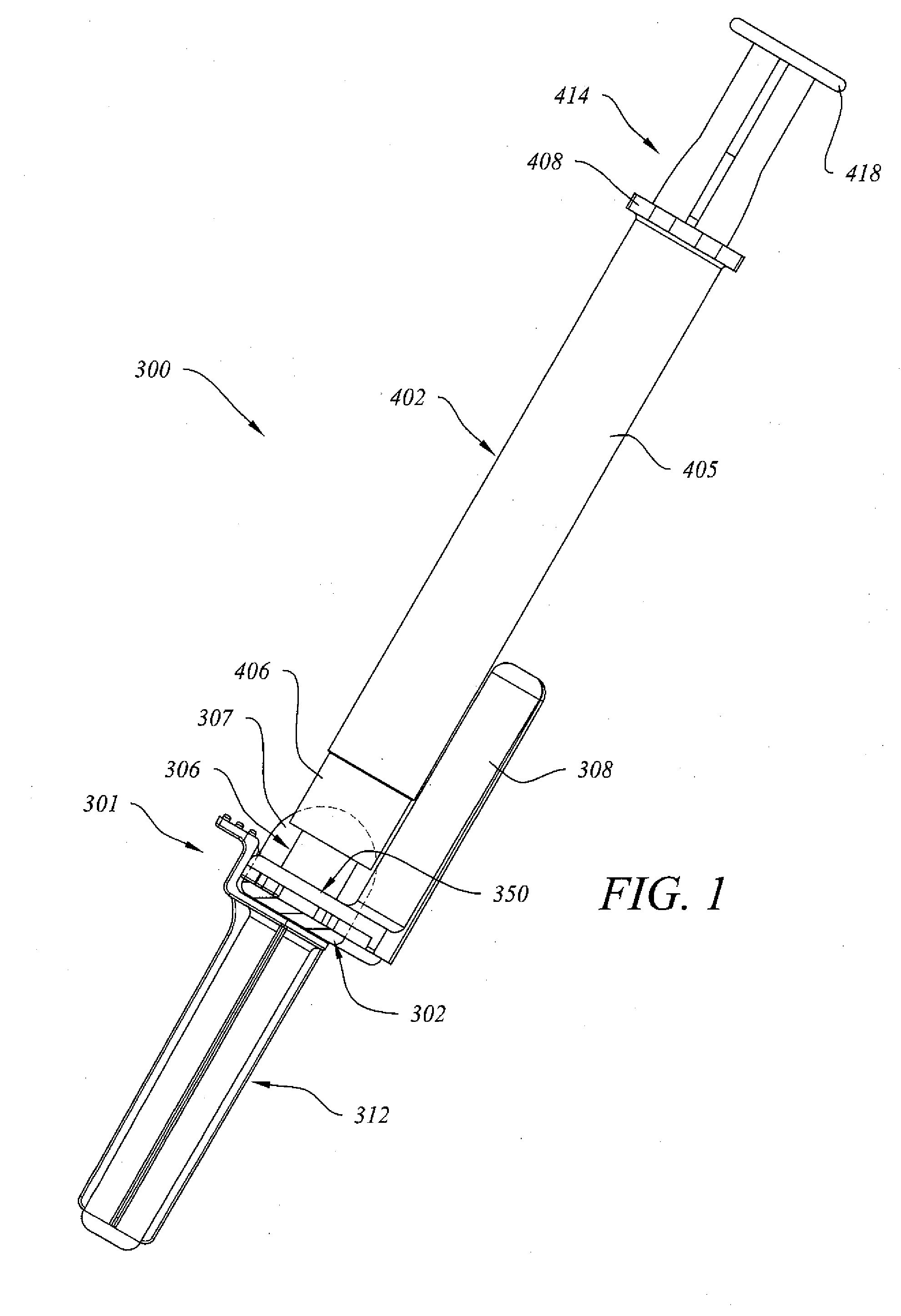
[0029]FIG. 1 depicts an assembled combination 300 comprising frontal attachment 301, which is one embodiment of the needle retraction apparatus of the invention, attached to a conventional syringe 402. Syringe 402 is desirably a conventional syringe having a luer lock connector 406. As such, syringe 402 can typically further comprise diametrically opposed finger grips 408, 410 at or near the rear of barrel 405, and a plunger assembly 414 that further comprises plunger handle 416 with thumb cap 418, plunger seal attachment boss 420, and plunger seal 422 that slidably engages the interior wall of barrel 405.

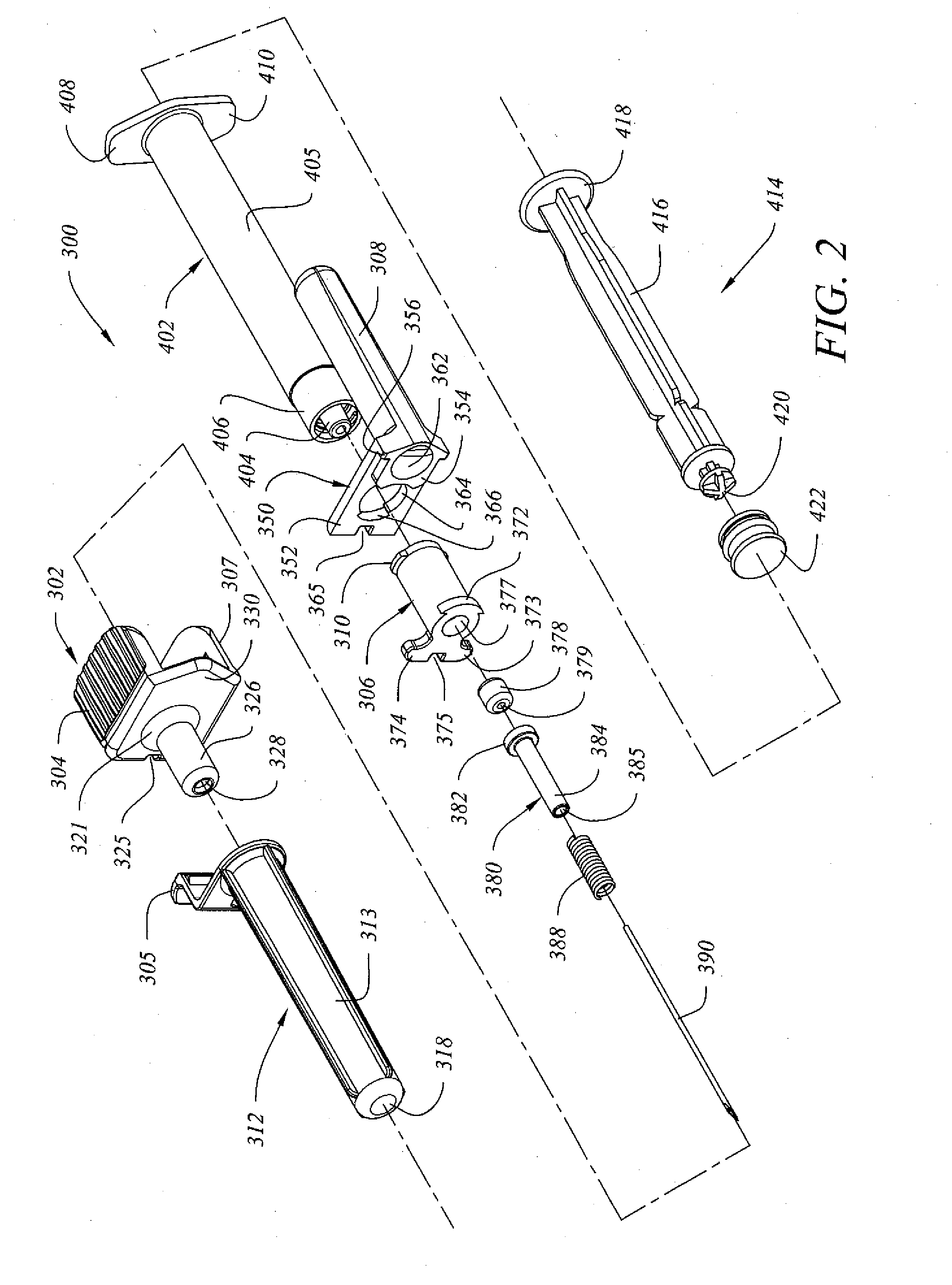
[0030]Frontal attachment 301 desirably comprises body 302, actuator 306, slide member 350, a forwardly projecting needle and needle retraction assembly (not visible in FIG. 1), and removable needle cover 312. Actuator 306 is rotatably mounted in slide member 350, which desirably further comprises rearwardly projecting tubular needle retraction chamber 308. In FIG. 1, in order to be...


PUM


Abstract

A needle retraction apparatus for a medical device such as a liquid infusion or collection device, the apparatus having a body, a needle retraction mechanism seated inside the body, a transverse slide member with an external needle retraction chamber, and a retraction actuator that is rotatable relative to the slide member, the retraction actuator being attachable to or made as part of the liquid infusion or collection device, whereby rotation of the device causes the slide member to move in a linear translational direction to reposition the retraction chamber in alignment with the needle retraction mechanism and allow retraction.

Description

BACKGROUND OF THE INVENTION[0001]1. Field of the Invention[0002]This invention relates to a needle retraction apparatus for medical devices. One aspect of the invention relates to a new needle retraction apparatus that can be attached to or manufactured together with, or as an integral part of, a medical device such as a syringe, catheter, or other liquid infusion or collection device. Another aspect of the invention relates to a needle retraction apparatus that is rotationally activated and cam operated. Another aspect of the invention relates to a needle retraction apparatus for a liquid infusion or collection device, the apparatus having a body with a forwardly facing, rearwardly biased needle, in which needle retraction is initiated by manually rotating an actuator to interrupt a fluid flow path through the apparatus and reposition a needle retraction chamber. Another aspect of the invention relates to a frontal attachment for a liquid infusion or collection device that comprise...

Claims


Application Information

Patent Timeline
Patent Type & Authority Applications(United States)
IPC IPC(8): A61M5/32A61B5/15
CPCA61M5/3232A61B5/1405A61B5/15003A61B5/150236A61B5/150244A61B5/150259A61B5/150389A61B5/150503A61B5/150633A61B5/150656A61B5/150732A61B5/150885A61B5/1535A61M5/3202A61M2005/3227
Inventor SHAW, THOMAS J.SMALL, MARKZHU, NI
Owner RETRACTABLE TECH INC
Why Eureka
Try Eureka