
Microfluidic disk for measuring microfluid and method for measuring microfluid

Inactive Publication Date: 2014-06-26
POSTECH ACAD IND FOUND
View PDF6 Cites 1 Cited by
  • Summary
  • Abstract
  • Description
  • Claims
  • Application Information

AI Technical Summary

Benefits of technology

The present invention provides a microfluidic disk and method for measuring microfluid efficiently and accurately. This allows for efficient conduct of microfluid flow tests using a disk-based microfluidic system.

Problems solved by technology

However, the precision of measurement of several microliters (1 to 10 μl) of fluids is not high, and the injection process of measured microfluid into the disk-based microfluidic system may face difficulties or cause volume loss.

Method used


Image

  • Microfluidic disk for measuring microfluid and method for measuring microfluid
  • Microfluidic disk for measuring microfluid and method for measuring microfluid
  • Microfluidic disk for measuring microfluid and method for measuring microfluid

Examples


Embodiment Construction

[0019]In the following detailed description, only certain exemplary embodiments of the present invention have been shown and described, simply by way of illustration. As those skilled in the art would realize, the described embodiments may be modified in various different ways, all without departing from the spirit or scope of the present invention.

[0020]Accordingly, the drawings and description are to be regarded as illustrative in nature and not restrictive. Like reference numerals designate like elements throughout the specification.

[0021]Further, the sizes and thicknesses of the elements shown in the drawings are arbitrarily shown for convenience of description, and thus embodiments are not limited to those illustrated.

[0022]In addition, unless explicitly described to the contrary, the word “comprise” and variations such as “comprises” or “comprising” will be understood to imply the inclusion of stated elements but not the exclusion of any other elements.

[0023]Hereinafter, a mic...


PUM


Abstract

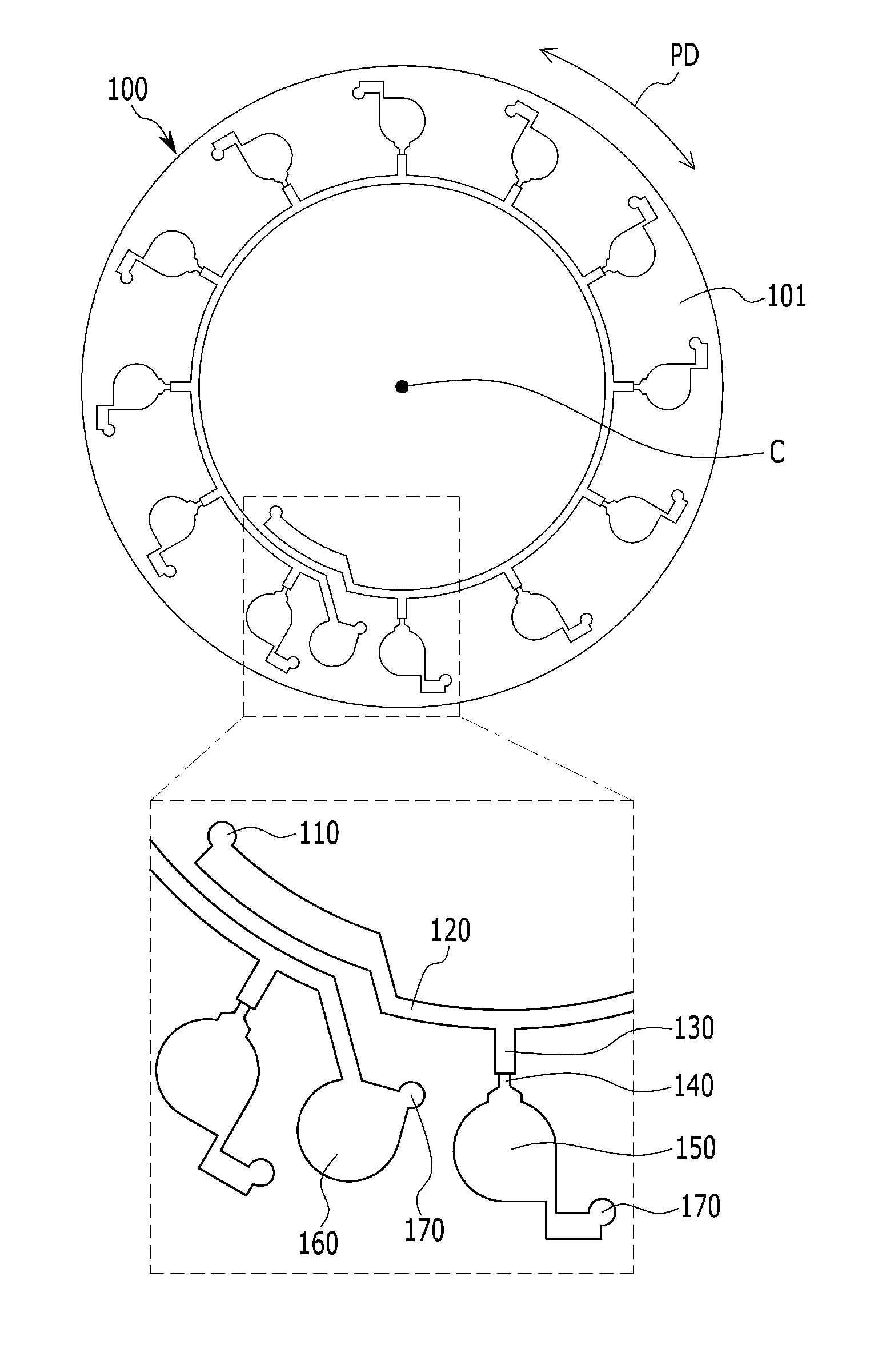
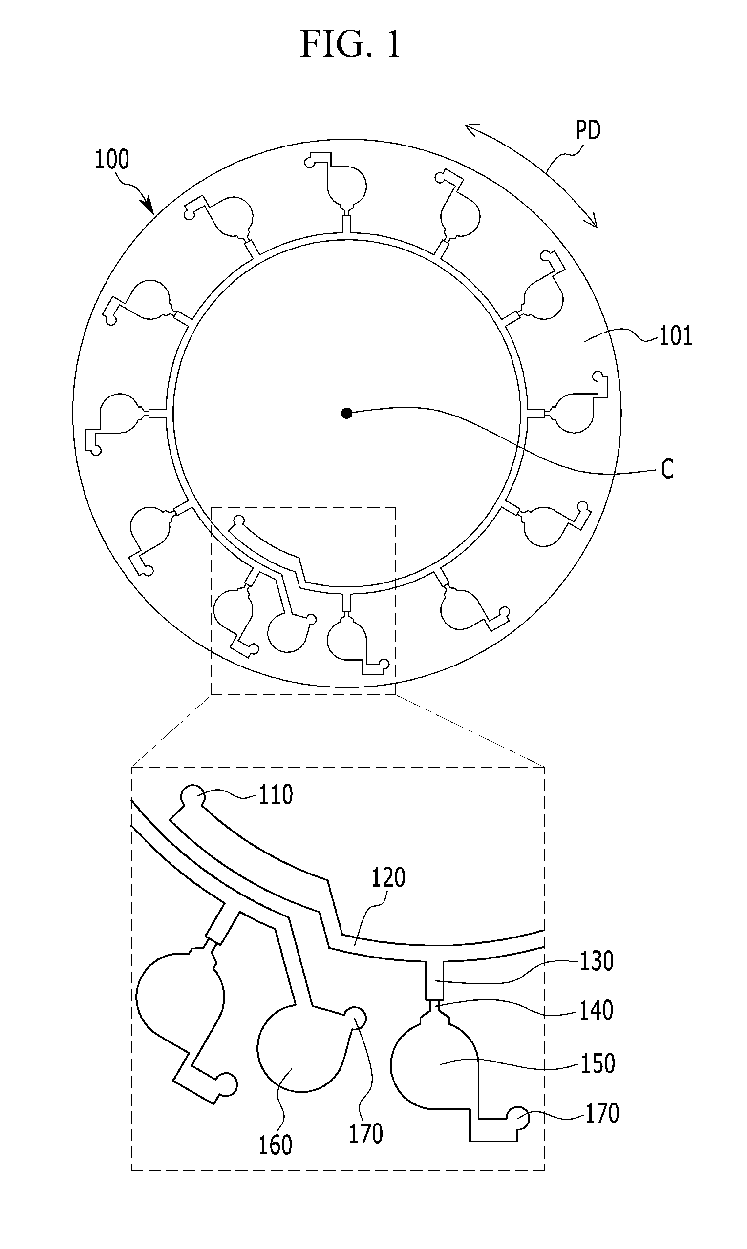
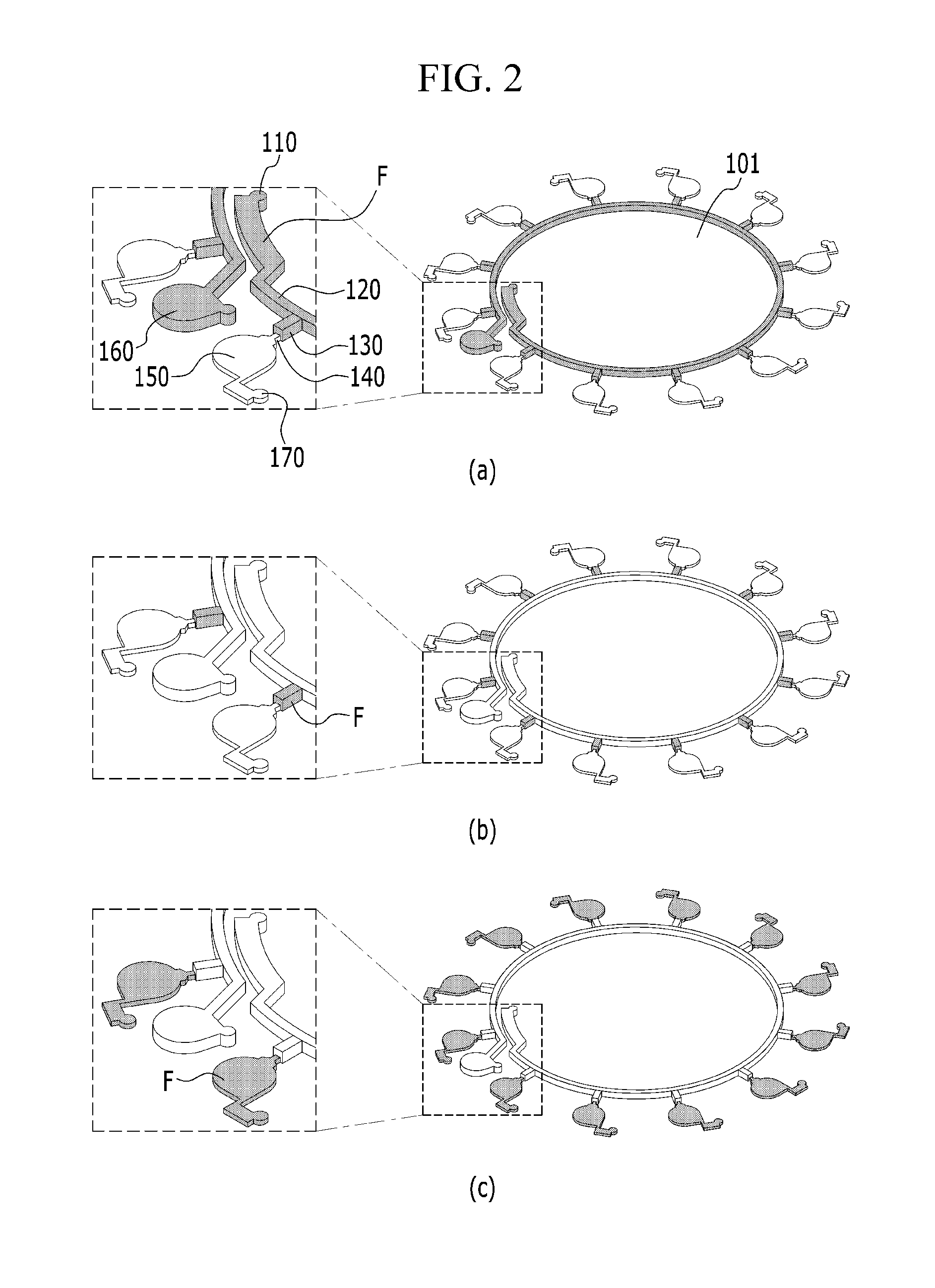
A microfluidic disk includes: a disk-shaped main body; an injection port; a distribution channel; measuring vessels; microvalves; a wastewater container; and holding containers.

Description

CROSS-REFERENCE TO RELATED APPLICATION[0001]This application claims priority to and the benefit of Korean Patent Application No. 10-2012-0151208 filed in the Korean Intellectual Property Office on Dec.21, 2012, the entire contents of which are incorporated herein by reference.BACKGROUND OF THE INVENTION[0002](a) Field of the Invention[0003]The present invention relates to a microfluidic disk for measuring microfluid and a method for measuring microfluid.[0004](b) Description of the Related Art[0005]In general, to conduct a microfluidic flow test on the separation, mixing, and reaction of microfluid, an adequate amount of fluid should be measured first.[0006]Conventionally, microfluid is measured using a precise measuring device, such as a pipet or cartridge, and then a microfluidic flow test is conducted using a disk-based microfluidic system. However, the precision of measurement of several microliters (1 to 10 μl) of fluids is not high, and the injection process of measured microf...

Claims


Application Information

Patent Timeline
IPC IPC(8): G01F3/02
CPCG01F3/02B01L3/502738B01L2300/0806B01L2300/0864B01L2400/0409B01L2400/0688G01N35/08G01N1/10G01N37/00
Inventor KIM, DONG SUNGLA, MOONWOO
Owner POSTECH ACAD IND FOUND
Learn More