Lubricating oil feeding mechanism in a swash type compressor

Inactive Publication Date: 2008-04-03
TOYOTA IND CORP
View PDF2 Cites 2 Cited by
  • Summary
  • Abstract
  • Description
  • Claims
  • Application Information

AI Technical Summary

Benefits of technology

[0008]An object of the present invention is to provide a lubricating oil feeding mechanism in a swash type compressor, which can efficiently conduct a large amount of lubricating oil in the swash plate chamber to the sliding part in the compressor so that the sliding part can become more reliable.
[0010]In the aspect of the present invention, lubricating oil adhered on the bolts is collected to the gap defined between the through holes and the bolts due to its own weight. The oil-collecting recess collects not only lubricating oil flowing downwardly on the side wall surface of the housing but also such lubricating oil gathered in the gap, and then feeds the lubricating oil collected therein by the oil-supplying groove. Lubricating oil guided to the oil-supplying groove is, then, led to the sliding part. Therefore, a large amount of lubricating oil in the swash plate chamber can efficiently be conducted to the sliding part of the compressor. Namely, this positive utilization of lubricating oil in the swash plate chamber enables the sliding part to be come more reliable during compressor operation.

Problems solved by technology

These solutions are, however, not sufficient in view of utilizing limited lubricating oil in the swash plate chamber more efficiently to obtain sufficient lubrication of the sliding part in the compressor.
In the compressors as mentioned above, such the lubricating oil adhered on the bolts cannot positively be used for the lubrication of the sliding part.

Method used


Image

  • Lubricating oil feeding mechanism in a swash type compressor
  • Lubricating oil feeding mechanism in a swash type compressor
  • Lubricating oil feeding mechanism in a swash type compressor

Examples


first embodiment

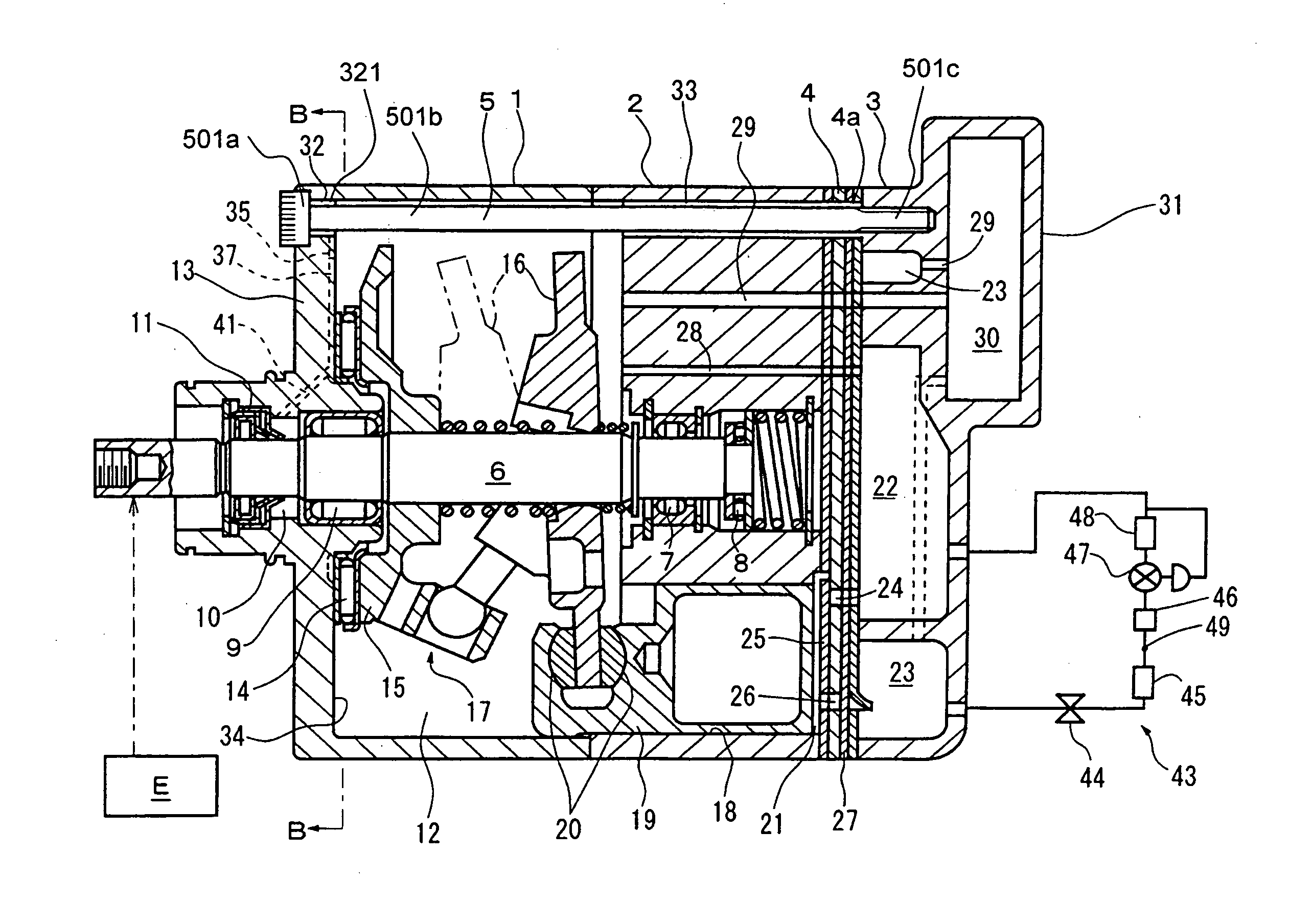
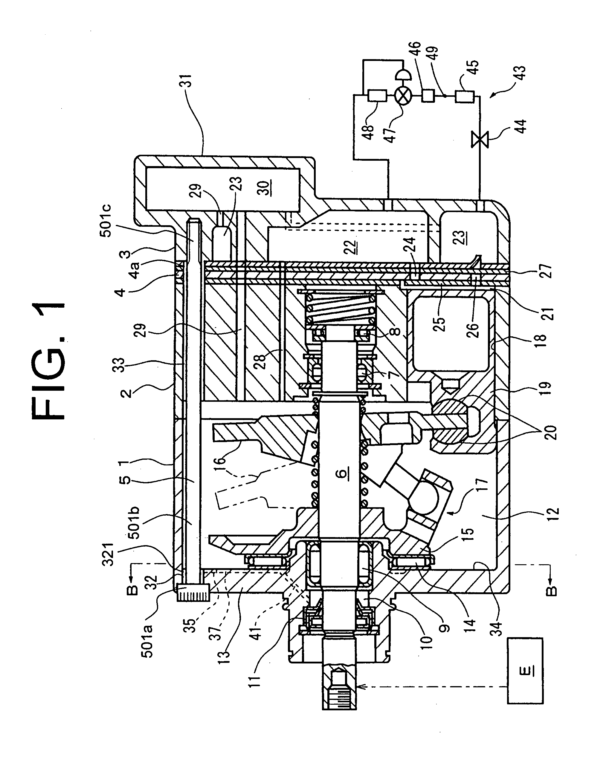
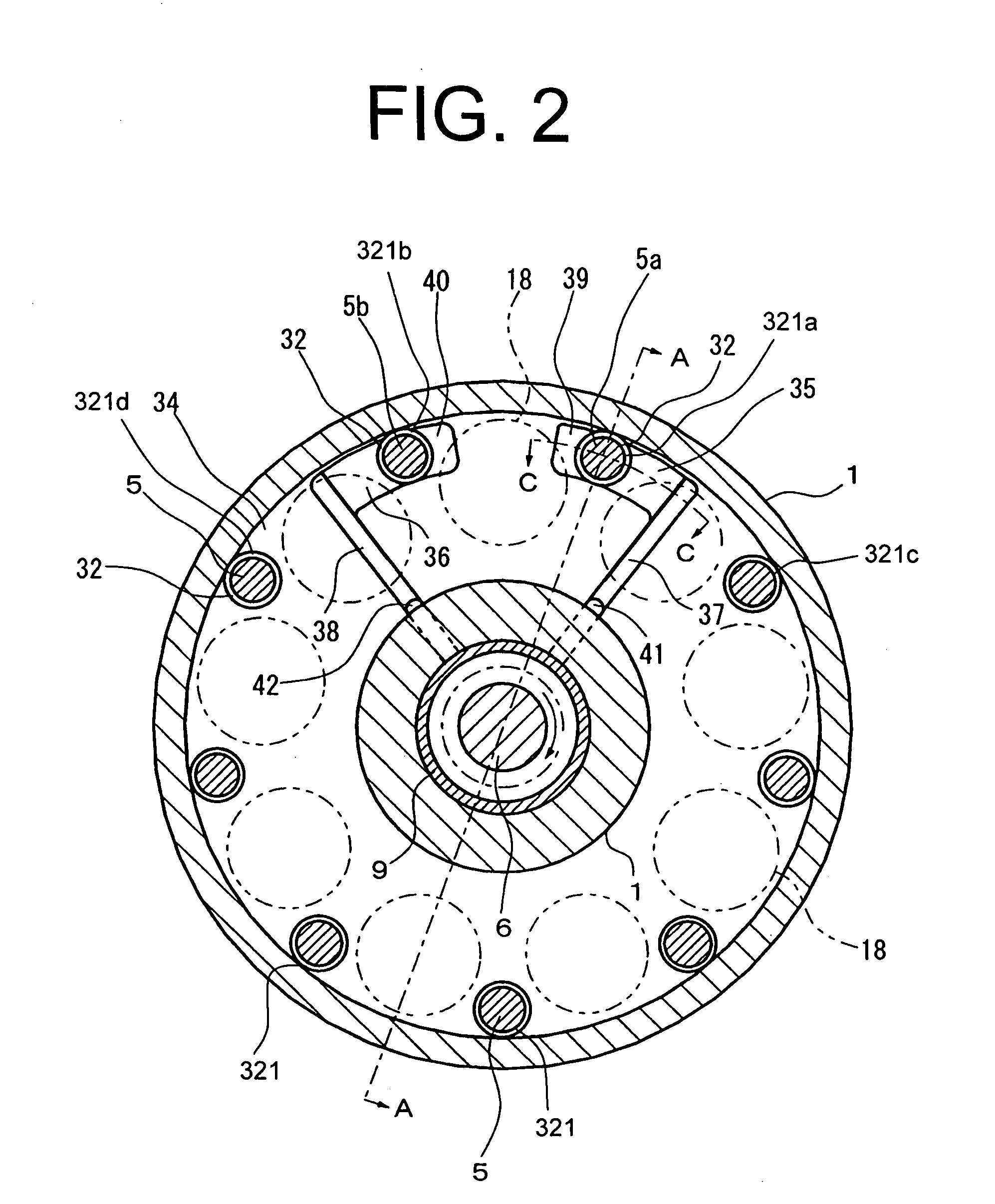
[0021]Referring to FIGS. 1, 2 and 3, the present invention is described hereinafter. FIG. 1 shows a variable displacement swash plate type compressor whose housing comprises a front housing 1, a cylinder block 2, a rear housing 3 and a valve plate unit 4 interposed between the cylinder block 2 and the rear housing 3. These housing elements 1, 2, 3 and 4 are fastened together as one body with a plurality (nine) of bolts 5 as shown in FIG. 2. The front housing 1 and the cylinder block 2 define a swash plate chamber 12 as a control chamber therebetween.

[0022]The front housing 1 and cylinder block 2 have a central axial bore formed therein respectively for receiving a drive shaft 6 which is rotatably supported by a pair of radial bearings 7 and 9 provided in the central axial bore, wherein one end of which is further supported by a thrust bearing 8 provided in the central axial bore of the cylinder block 2. Furthermore, in the central axial bore, a shaft seal 11 is disposed between the ...

second embodiment

[0051]Since stress concentration is likely to take place around the first bore 32 under strong fastening power by the bolts 5, in this case, it may be difficult in view of the strength required for the front housing 1 that an oil-collecting recess 50 is formed being connected to all around the circumference of the first bore 32 with a cutting process. however, the connection groove 51 connected with the first bore 32 is arranged narrower than the diameter of the first bore 32. Therefore, the stress concentration to be generated around the first bore 32 can be reduced.

[0052]FIG. 5 shows a lubricating oil feeding mechanism according to a third embodiment. In the third embodiment, component parts and elements corresponding to those of the above first embodiment are indicated by identical reference numerals, and a description thereof is omitted. What is different from the first embodiment is that a sub oil-collecting recess 54 extends over two of the gaps 321a, 321b to connect the gap ...

fourth embodiment

[0064]In the fourth embodiment, in addition to the lubricating oil feeding mechanism described before, a first sub oil-collecting recess connects the gap 321b to a gap 321d which is in the upper position with respect to the shaft seal 11 as sliding part to be lubricated in the housing in an operating state of the mounted compressor. Also, a second sub oil-collecting recess is connected to the gap 321b, and an oil-collecting recess is connected to the gap 321d, the oil-collecting recess being connected to an oil-supplying groove. Although both of those mechanism are adopted together so as to collect lubricating oil gathered in the gaps 321a, 321b, 321c and 321d, only one of the described mechanism might be used to improve the lubricativity.

[0065]In the fourth embodiment, the oil-supplying groove 58 is connected to the sub oil-collecting recess 56. In this embodiment, the sub oil-collecting recess 56 represents an oil-collecting recess, and the oil-collecting recess 55 represents a su...


PUM


Abstract

Lubricating oil feeding mechanism has an oil-collecting recess and an oil-supplying groove formed on the wall of the housing. The oil-collecting recess connects a gap defined between the through hole and the bolt to the oil-supplying groove, the gap being in the upper position with respect to a sliding part to be lubricated in the housing in an operating state of the mounted compressor. The oil-collecting recess extends from the gap in the circumferential direction of the drive shaft, and the oil-supplying groove upwardly extends toward the oil-collecting recess. The oil-supplying groove is arranged so as to guide lubricating oil to the sliding part. Lubricating oil adhered on the bolt can be collected to the oil-collecting recess via the gap, and is fed to the sliding part through the oil-supplying groove. Therefore, a large amount of lubricating oil in a swash plate chamber can be utilized to lubricate the sliding part.

Description

BACKGROUND OF THE INVENTION[0001]1. Field of the Invention[0002]The present invention relates to a swash type compressor and, more particularly, to an improved lubricating oil feeding mechanism for such compressors.[0003]2. Description of the Related Art[0004]In general, swash type compressors with variable or fixed displacement mechanism have a swash plate chamber to arrange a swash plate therein. The compressors also have a bearing for supporting a drive shaft coupled to the swash plate and a shaft seal for preventing refrigerant gas in the swash plate chamber from leaking outside. The bearing and the shaft seal are to be lubricated by lubricating oil contained in refrigerant gas in the swash plate chamber.[0005]Japanese Utility Model Application Laid-Open Publication No. 57-112082 discloses a swash type compressor having a cylinder block forming cylinder bores and a swash plate chamber therein; a drive shaft rotatably supported on the cylinder block via radial bearings; a swash p...

Claims


Application Information

Patent Timeline
IPC IPC(8): F04B1/12F01M11/04
CPCF04B27/109
Inventor IMAI, TAKAYUKIMURASE, MASAKAZUNAGANO, HIROKIYOKOMACHI, NAOYAFUKANUMA, TETSUHIKO
Owner TOYOTA IND CORP
Why Eureka
Try Eureka