Synchronous folding device

a technology of a synchronous folding device, which is applied in the direction of door/window fittings, construction, etc., can solve the problems of inability to close or open the electronic apparatus accurately and smoothly, the support strength of the operation angle and the smooth and light operation to fold and unfold are limited, and the demand for light operation cannot be achieved

Active Publication Date: 2014-06-26
FIRST DOME
View PDF7 Cites 42 Cited by
  • Summary
  • Abstract
  • Description
  • Claims
  • Application Information

AI Technical Summary

Benefits of technology

[0014]In an embodiment, the two ends of the driving joint assembly are formed with insertion heads to be insert

Problems solved by technology

For a long time, subject to the configuration of the spindle and the spindle sleeve, the support strength of the operation angle and the smooth and light operation to fold and unfolded are limited.
The coord

Method used


Image

  • Synchronous folding device
  • Synchronous folding device
  • Synchronous folding device

Examples


Embodiment Construction

[0030]Embodiments of the present invention will now be described, by way of example only, with reference to the accompanying drawings.

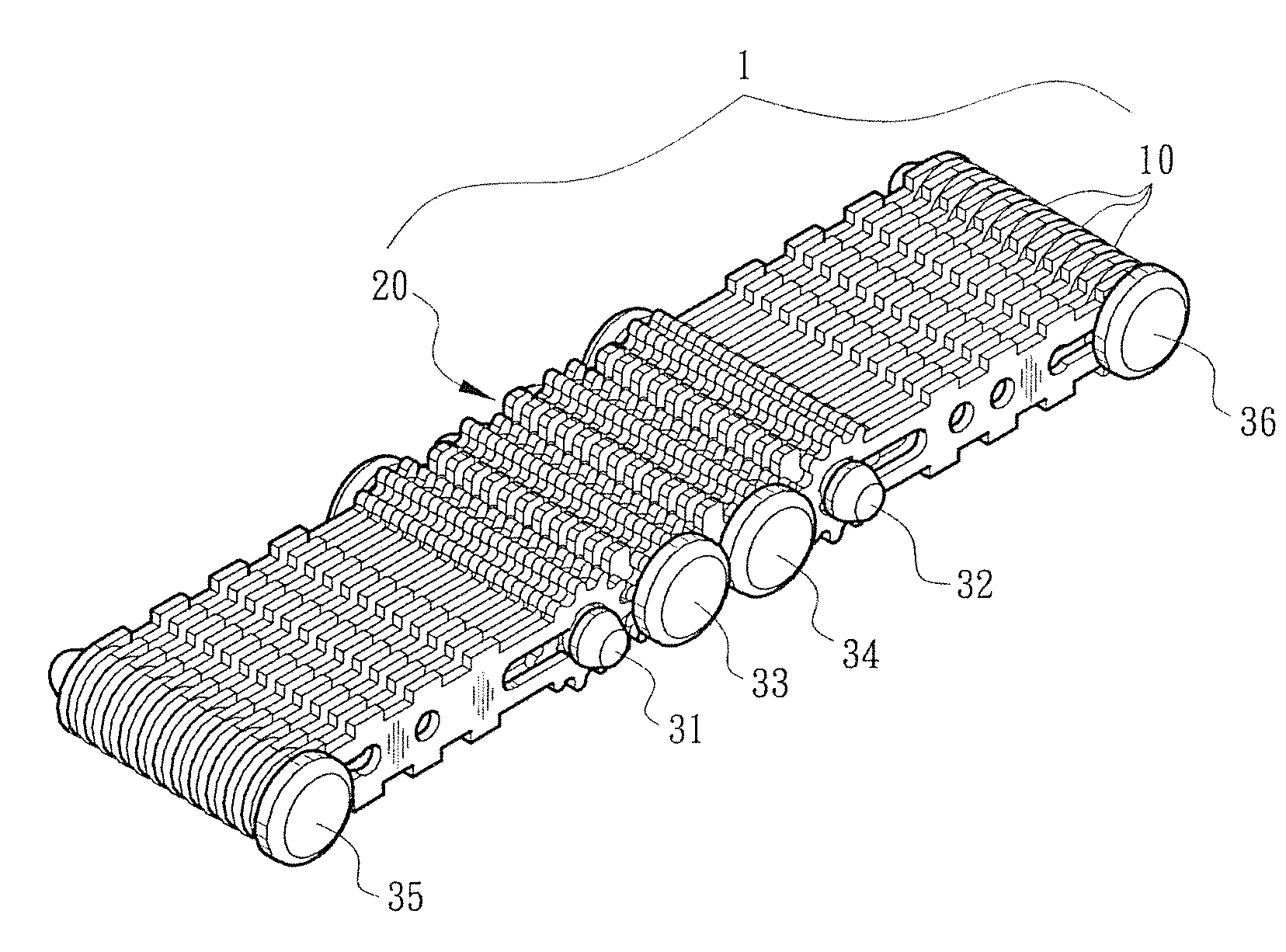
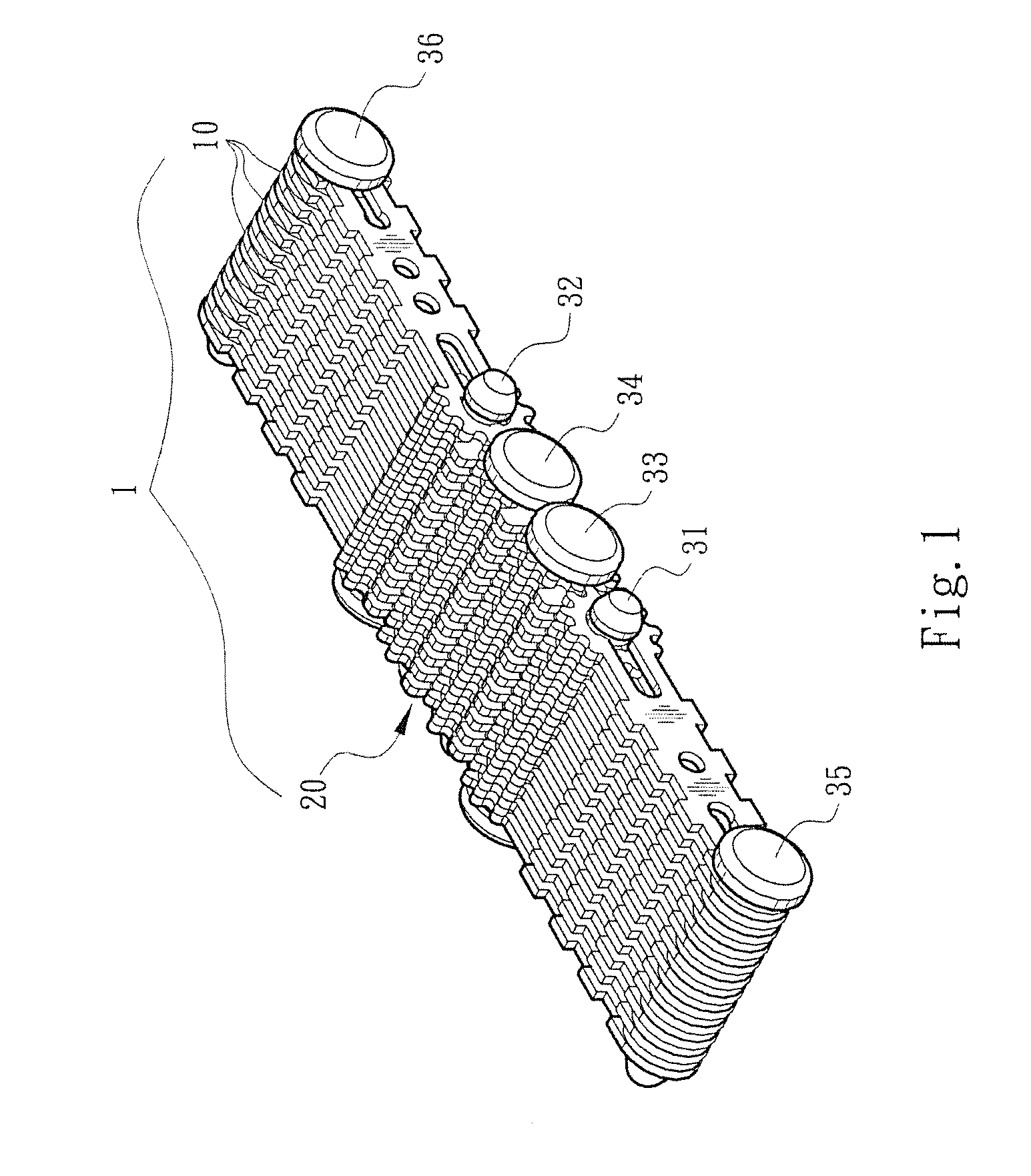
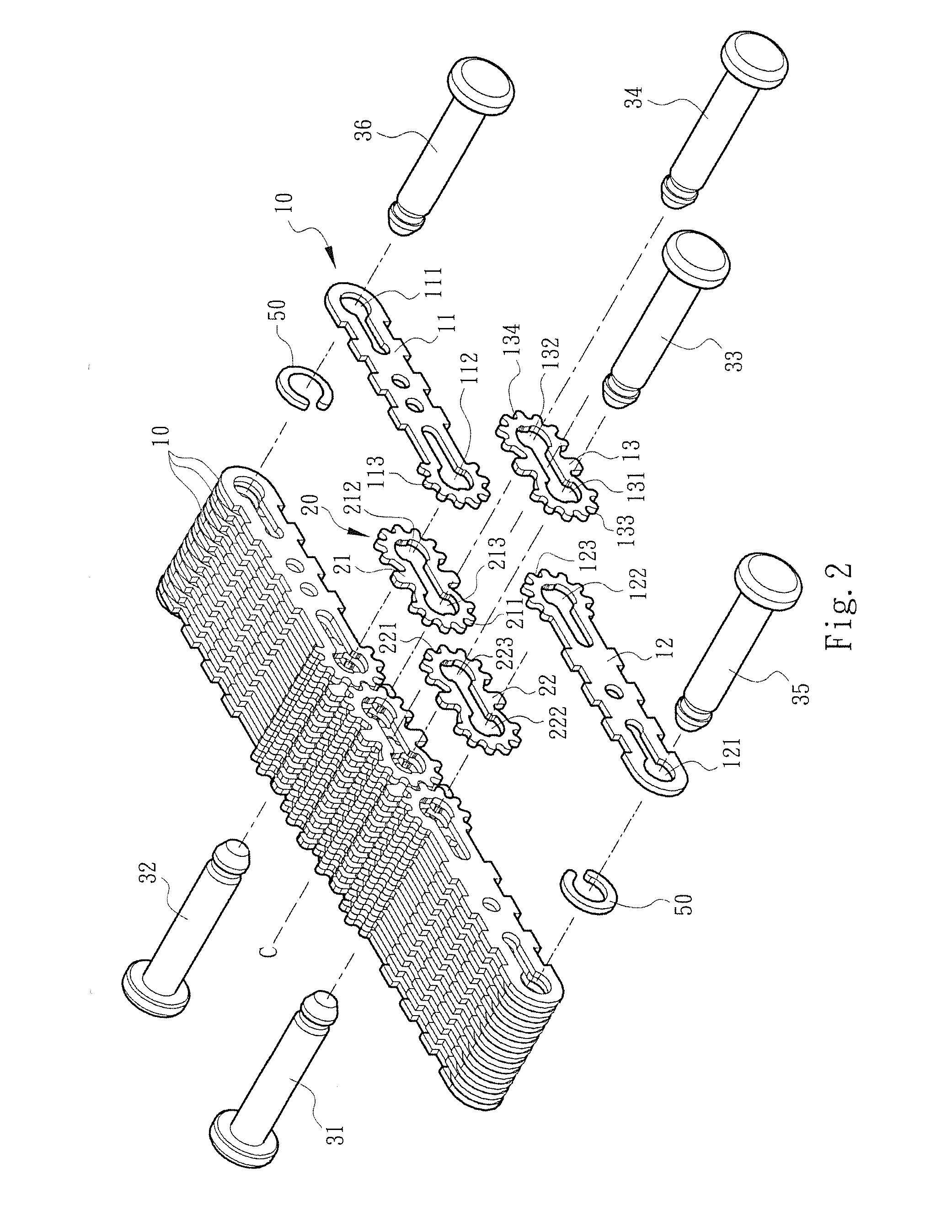
[0031]Referring to FIG. 8, FIG. 9 and FIGS. 12-14, the present invention comprises two opposing first and second folding members 81, 82 and a multi-joint rotary axle structure 1 mounted between the first and second folding members 81, 82. The multi-joint rotary axle structure 1 has two ends which can be folded or unfolded synchronously. As shown in FIG. 1 to FIG. 3, the multi-joint rotary axle structure 1 comprises at least one driving joint assembly 10 and at least one driven joint assembly 20, as shown in FIG. 3, to cooperate with a plurality of axle pins to constitute the multi-joint rotary axle structure 1.

[0032]In order to explain the connection relationship between the parts, the central line C as shown in FIG. 2 is as the reference line to define an “inner” direction which is close to the central line C and an “outer” direction which is far fro...


PUM


Abstract

A synchronous folding device includes two opposing folding members and a multi-joint rotary axle structure mounted between the two folding members. The multi-joint rotary axle structure has two ends which can be folded or unfolded synchronously. The multi-joint rotary axle structure includes a driving joint assembly and a driven joint assembly. The driving joint assembly includes two opposing joint plates and a middle link plate. Two ends of the driving joint assembly are respectively connected to the two opposing folding members. Each joint plate of the driving joint assembly can be turned free through plural turning centers so that both ends can be closed or opened synchronously for the folding device to be folded or unfolded accurately.

Description

BACKGROUND OF THE INVENTION[0001]1. Field of the Invention[0002]The present invention relates to a synchronous folding device, and more particularly to a synchronous folding device for an electronic apparatus. The synchronous folding device comprises two opposing folding members and a multi-joint rotary axle structure mounted between the two folding members. The multi-joint rotary axle structure has two ends which can be folded or unfolded synchronously so that both ends of the electronic apparatus can be closed or opened smoothly.[0003]2. Description of the Prior Art[0004]Nowadays, an electronic apparatus having opposing folding members (such as foldable monitor, handheld game console, PDA, cell phone, electronic book, outer casing of an electronic product, or the like) comprises a base, a foldable upper cover, and a pivotal device connected between the base and the upper cover. The upper cover is turned about the pivotal device to fold or unfold the two folding members. The pivota...

Claims


Application Information

Patent Timeline
IPC IPC(8): E05D3/14
CPCE05D3/14E05Y2201/62Y10T74/1888
Inventor HSU, AN SZUDAI, WAY HAN
Owner FIRST DOME
Why Eureka
Try Eureka