

Medical sterile packaging and packaging method
a technology of medical sterility and packaging, applied in the direction of packaging goods, rigid containers, internal osteosynthesis, etc., can solve the problems of not being able to ensure cleaning according to specifications, unable to provide sterile implants provided for surgical intervention, and not being able to be soiled in the course of intervention
- Summary
- Abstract
- Description
- Claims
- Application Information
AI Technical Summary
Benefits of technology
Problems solved by technology
Method used
Image

Examples
first embodiment
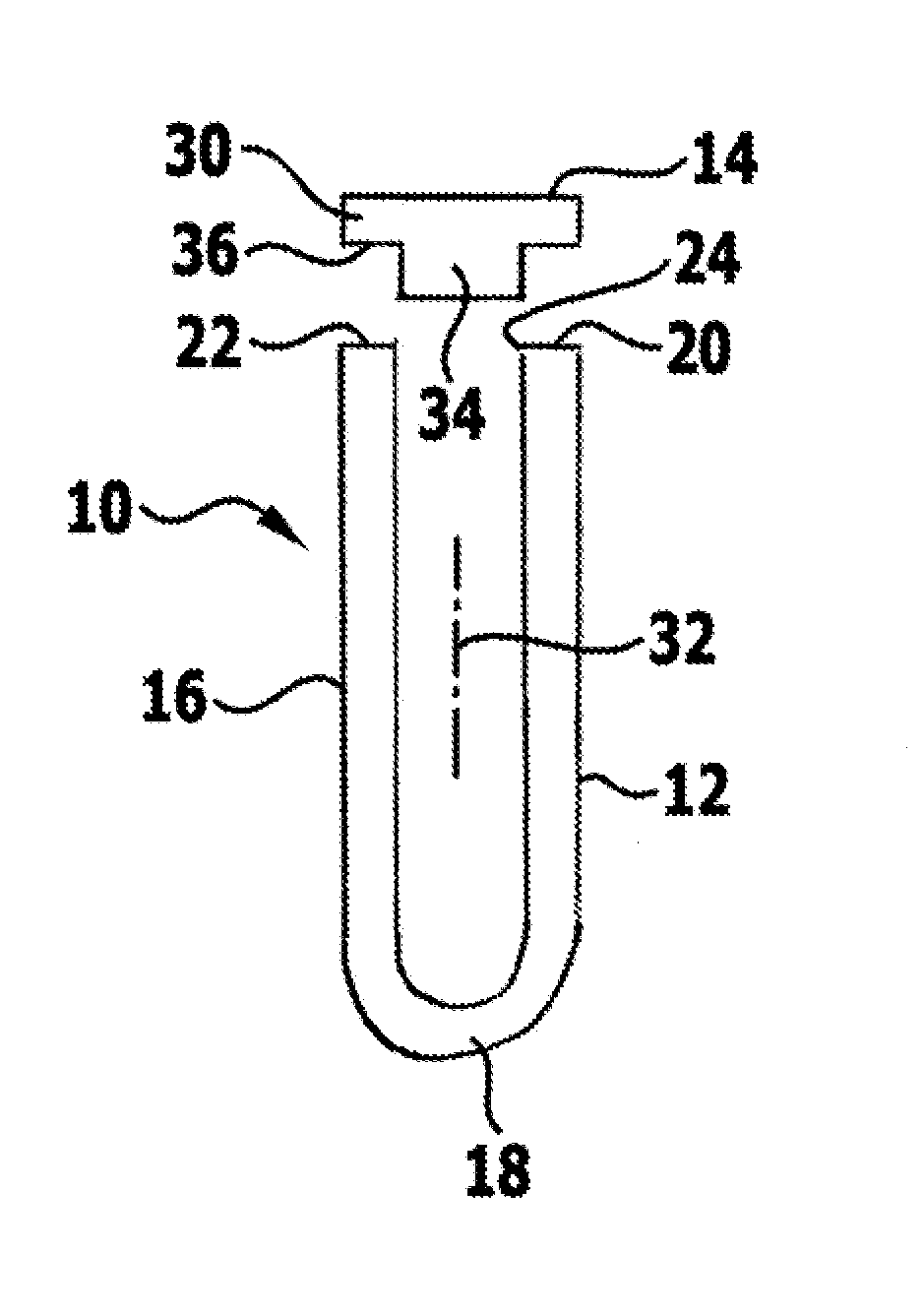
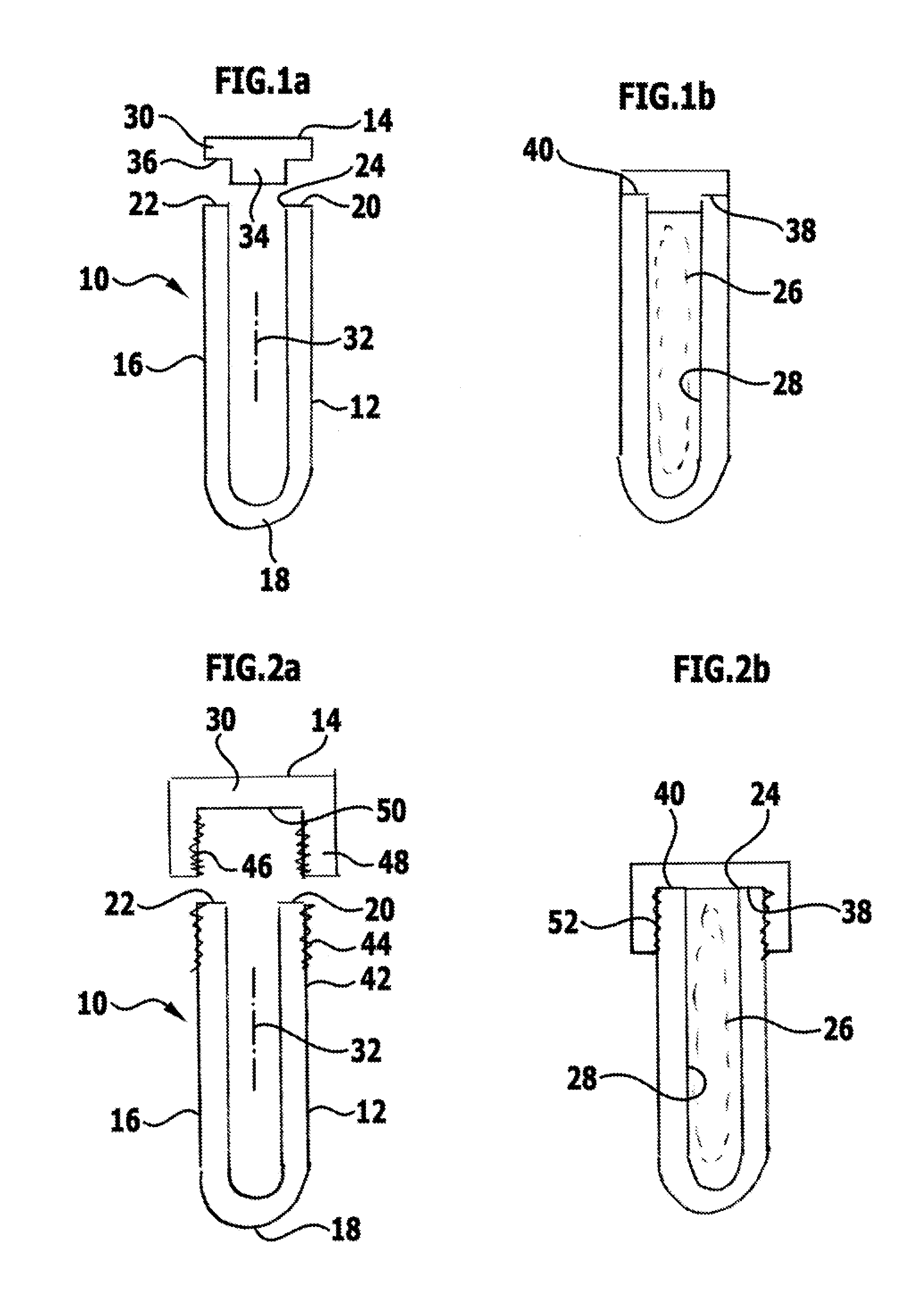
[0072]FIG. 1 schematically shows a sterile packaging designated by the reference numeral 10 as a whole. It comprises a container 12 and a closure element 14. Both the container 12 and the closure element 14 are preferably rotationally symmetrical. The container 12 is produced from a tube 16, which is closed at its one end 18 by hammering, so a substantially half hollow sphere is produced. The opposite end 20 defines an annularly closed edge face 22, which is directed away from the end 18 and surrounds an introduction opening 24, through which an implant 26, which is formed for temporary or permanent insertion in a human or animal body, can be introduced into a receiving space 28 defined by the sterile packaging 10.
[0073]The closure element 14 is in the form of a circular disc 30, from which a cylindrical projection 34 projecting coaxially with respect to a longitudinal axis 32 defined by the container 12 extends away. The projection 34 is dimensioned such that it can be introduced i...
fourth embodiment
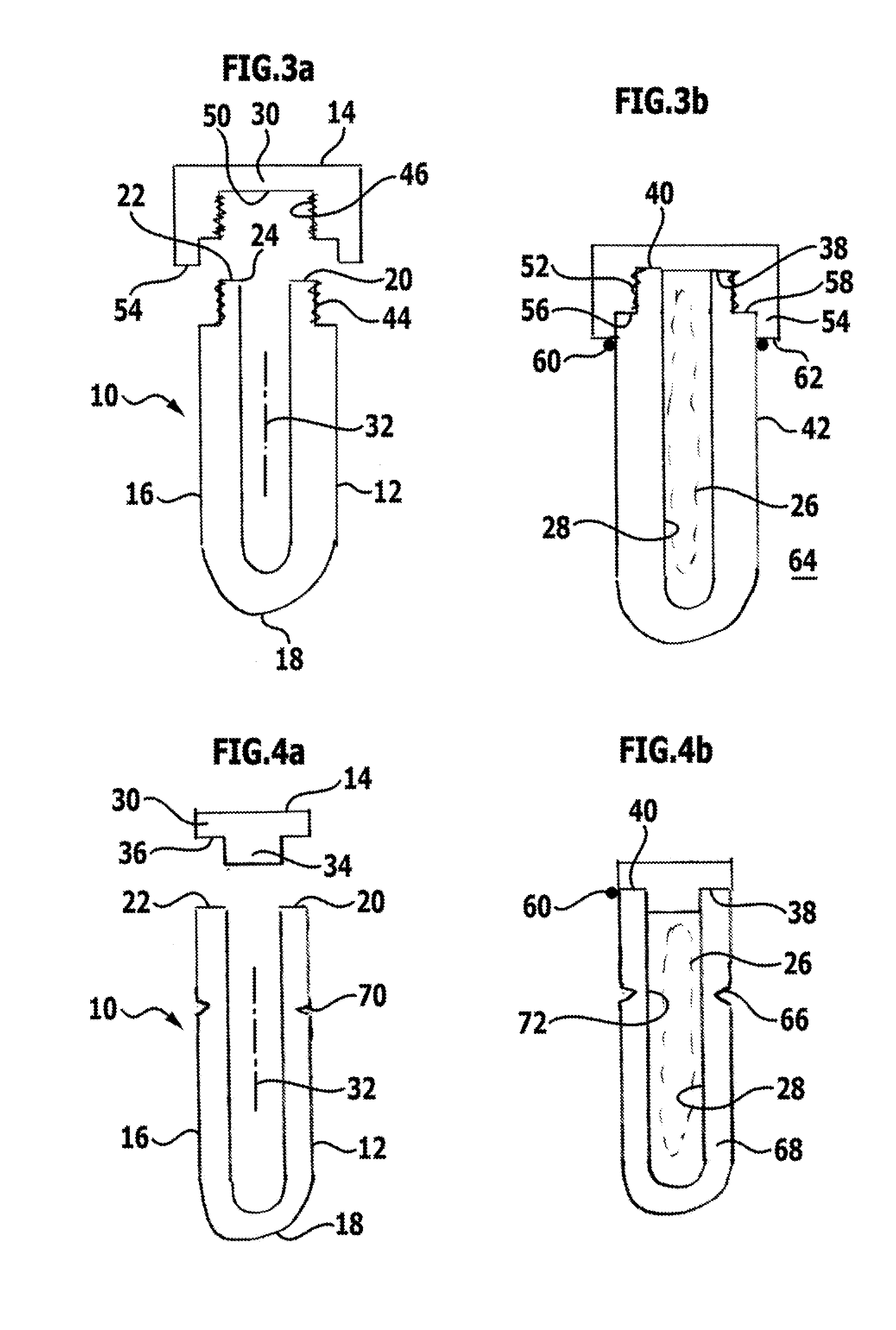
[0081]a sterile packaging 10 is schematically shown in FIGS. 4a and 4b. With respect to its structure, it substantially corresponds to the embodiment of the sterile packaging 10 shown in FIGS. 1a and 1b and differs therefrom merely in that a predetermined breaking point 66 is provided on the container 12. The predetermined breaking point 66 is formed by a weakening of the material forming the container 12, specifically by a reduction in a thickness of a wall 68 of the container 12. The reduction in the thickness of the wall 68 to form the predetermined breaking point 66 is realised by a groove 70, which annularly surrounds the container 12 on its outside 42 and has a V-shaped cross section.
[0082]To open the sterile packaging 10, the predetermined breaking point 66 can be severed by unscrewing or snapping off and the implant 26 can then be removed through the removal opening 72 formed in the region of the predetermined breaking point 66.
fifth embodiment
[0083]a sterile packaging 10 is schematically shown in FIGS. 5a and 5b. It comprises a trough-like container 12, which has an open upper side 74, which is closed by a substantially plate-shaped closure element 14. A peripheral wall 68 projecting from a base of the container 12 in the direction of the closure element 14 is folded over in the direction of the receiving space 28 and engages over a flange-like peripheral edge 78, which is directed away from the base 76, of the closure element 14. By means of this folding over or beading, the closure element 14 is connected to the container 12 in a permanent and gas-tight manner. The beading 80 can additionally be secured by welding or gluing.
[0084]A groove 70 facing away from an outside 82 of the closure element 14 and running parallel to the edge 78 is furthermore provided on the closure element 14 to form a predetermined breaking point 66. A tool element 84 is connected to the closure element 14, specifically in the form of a pull mem...
PUM
 Abstract
Description
Claims
Application Information