Shaft seal ring with Anti-rotation features

a technology of shaft seals and features, applied in the field of seals, can solve the problems of compromising the integrity of the seal, affecting the sealing effect, and prone to wear on the surface, so as to reduce the wear of the seal and ensure the sealing

Inactive Publication Date: 2014-06-26
PARKER HANNIFIN CORP
View PDF3 Cites 5 Cited by
  • Summary
  • Abstract
  • Description
  • Claims
  • Application Information

AI Technical Summary

Benefits of technology

[0006]The present invention provides an improved rotational shaft seal ring for use in applications involving high rotational speeds and high pressure fluids. The shaft seal ring of the present invention reduces seal wear as compared to conventional configurations, while maintaining an effective seal against leakage of the operating fluids of the application.
[0007]Accordingly, an aspect of the invention is a shaft seal with enhanced anti-rotation features. In exemplary embodiments the shaft seal is a bi-material seal ring including an elastomeric component bonded to a seal contact component. The seal contact component is a rigid or semi-rigid material, such as for example polytetrafluroethylene (PTFE), commonly sold under the trade name Teflon®. The PTFE component material accommodates the high rotational speed and high fluid pressure in the typical applications. The elastomeric component provides elastic properties to allow an energized stretch fit of the seal during installation without the need for a joint. The elimination of a joint avoids creation of a leak path that would be associated with such joint. The elastomeric component energizes the seal to provide a tight seal fit and further reduce leakage.
[0008]The elastomeric component includes a plurality of anti-rotation features that are spaced intermittently about a circumference of the elastomeric component. The anti-rotation features are configured on the elastomeric component to prevent rotational slippage in the application groove or bore that could negatively impact seal performance. The intermittent anti-rotation features are contoured to have substantially a “tear drop” shape to facilitate installation while providing improved grip to prevent slippage as compared to conventional configurations. The anti-rotation features also permit a thinner axial seal profile, which reduces seal volume fill, and which in turn reduces the radial seal force resulting in less drag and less heat generation about the seal as compared to conventional configurations. Less seal wear, therefore, occurs, thereby providing enhanced seal performance and longer seal life as compared to conventional configurations.

Problems solved by technology

The conventional configuration, however, has proven deficient.
In particular, the large interference surface tends to experience a high level of wear, ultimately compromising the integrity of the seal.
Rotational slippage may therefore occur, resulting in even further wear of the seal and ultimately a loss of seal integrity.
In addition, circumferential anti-rotation rings have a substantial seal volume as compared to the void volume within the application housing structure, and therefore “over-stuffing” of seal material within the shaft often occurs.
Such over-stuffing of the seal material exacerbates the wear problems of conventional shaft seal rings.

Method used


Image

  • Shaft seal ring with Anti-rotation features
  • Shaft seal ring with Anti-rotation features
  • Shaft seal ring with Anti-rotation features

Examples


Embodiment Construction

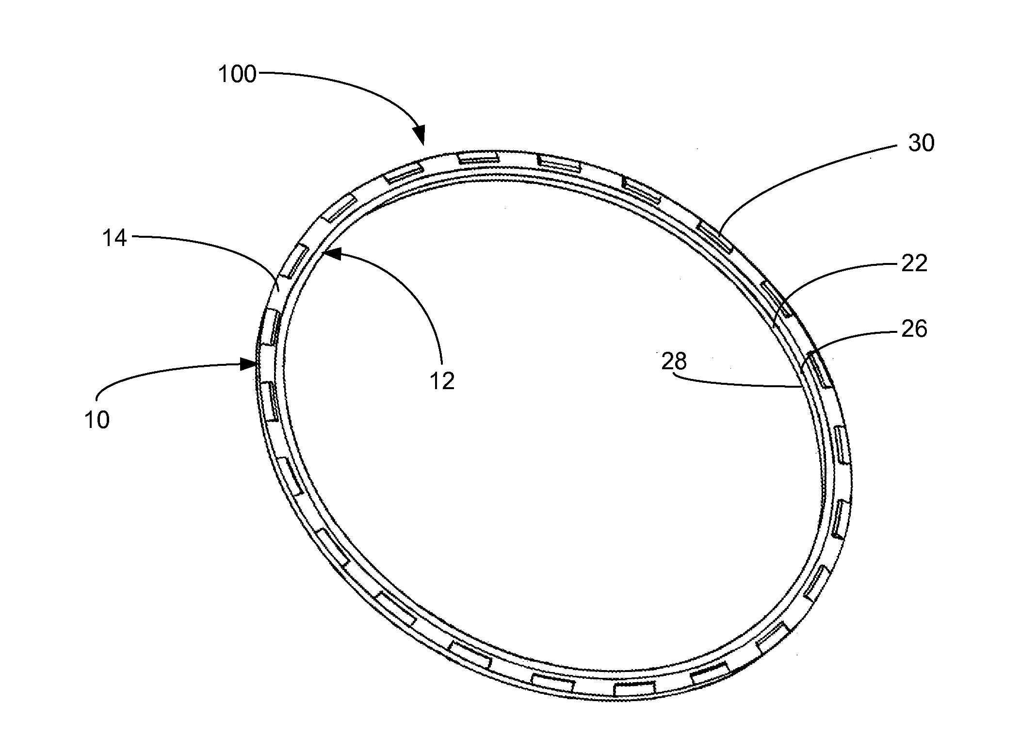
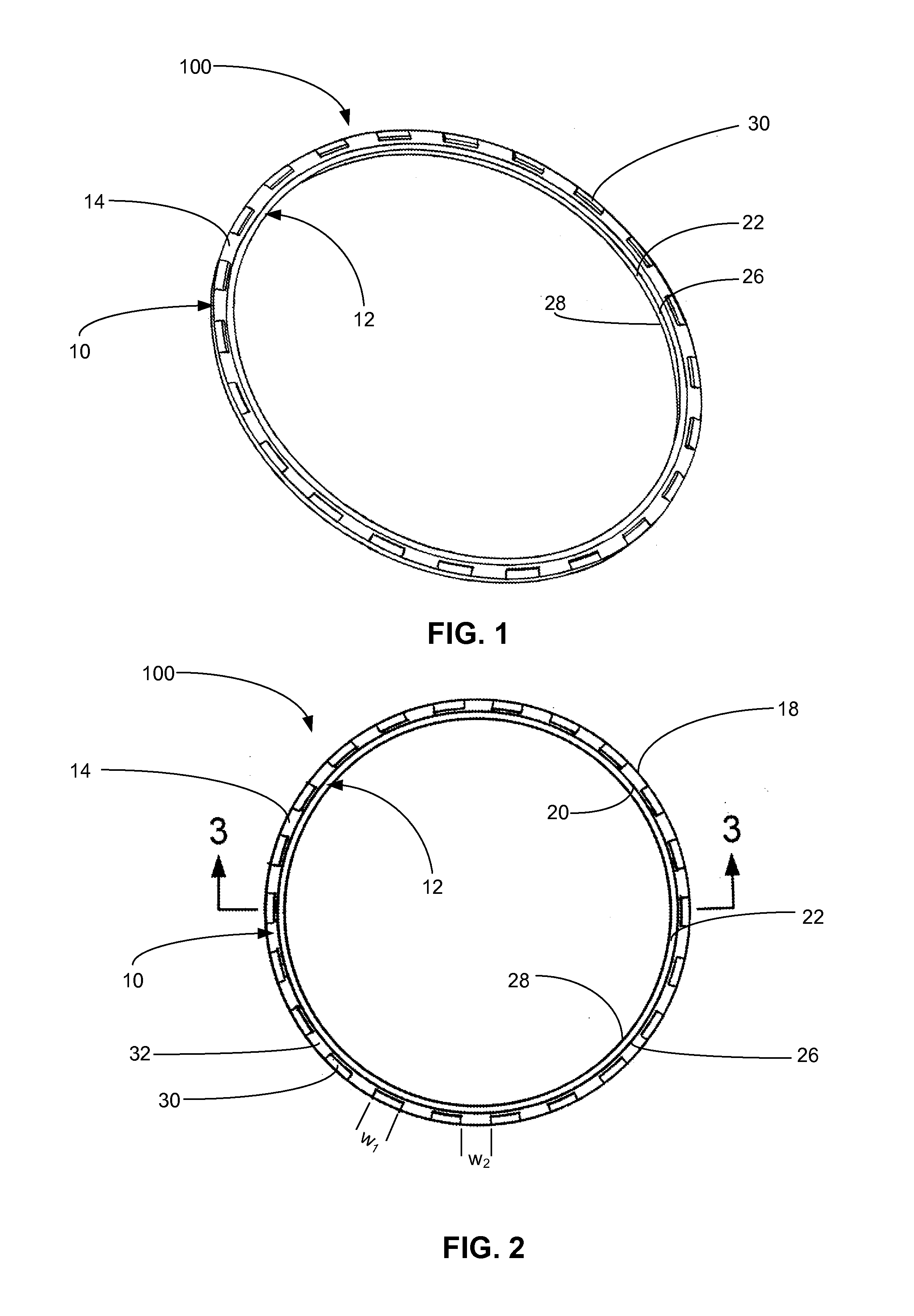
[0023]Embodiments of the present invention will now be described with reference to the drawings, wherein like reference numerals are used to refer to like elements throughout. It will be understood that the figures are not necessarily to scale.

[0024]FIGS. 1-3 depict various views of an exemplary embodiment of a shaft seal 100 with a seal ring configuration. In particular, FIG. 1 is a schematic diagram depicting a three-dimensional perspective view of an exemplary shaft seal 100. FIG. 2 is a schematic diagram depicting a top view of the shaft seal 100 of FIG. 1, and FIG. 3 is a schematic diagram depicting a side cross-sectional view of the shaft seal 100 of FIGS. 1-2. The shaft seal 100 includes a first component 10 and a second component 12. The shaft seal has a ring structure, and the first and second components are ring structures that are concentrically adjacent each other. In this embodiment, the first component 10 is an elastomeric component, and the second component 12 is a no...


PUM


Abstract

A shaft seal includes an elastomeric component that includes a plurality of anti-rotation features spaced intermittently about a circumference of the elastomeric component, and a seal contact component that is bonded to the elastomeric component. Each of the plurality of anti-rotation features is a rib structure. The rib structure of each of the plurality of anti-rotation features may extend from adjacent the outer diameter face and widen toward the inner diameter face, or may extend from adjacent the inner diameter face and widen toward the outer inner diameter face, to form substantially a tear drop shape. A shaft seal assembly includes the described shaft seal, and an application housing structure including a bore that receives at least a portion of the shaft seal. The seal contact component is received within the bore, and the application housing structure is configured to rotate relative to the shaft seal.

Description

FIELD OF THE INVENTION[0001]The present invention is directed to a seal configured for use in high rotational speed and high fluid pressure applications, and particularly to a bi-material shaft seal ring having anti-rotation features.BACKGROUND OF THE INVENTION[0002]Various sealing applications are provided in high rotational, high fluid pressure environments. Examples of such environments include automotive and light truck automatic transmission systems, limited slip differential clutch systems in engine transmissions, tire inflation systems, and the like. Such systems require rotating shaft seals to seal fluids, such as oils or air, operating under high pressure.[0003]In conventional shaft seals, a bi-material seal ring is provided in which an elastomeric component is bonded to a substantially rigid or semi-rigid seal contact component. The seal contact component preferably is a low-friction material. In operation, the seal is positioned within an application groove or bore, and t...

Claims


Application Information

Patent Timeline
Patent Type & Authority Applications(United States)
IPC IPC(8): F16J15/34
CPCF16J15/34F16J15/064
Inventor LUCHS, BERNDT L.
Owner PARKER HANNIFIN CORP
Why Eureka
Try Eureka