Liquid ejecting head, liquid ejecting apparatus, piezoelectric element, and method for manufacturing piezoelectric element

a liquid ejecting head and liquid ejecting technology, which is applied in the direction of piezoelectric/electrostrictive transducers, inking apparatus, generators/motors, etc., can solve the problems of electrodes or wiring layers, electrical corrosion at the boundaries, and similar problems may be encountered with the use of liquid ejecting heads, so as to improve the piezoelectric properties of the piezoelectric layer and reduce costs

Active Publication Date: 2014-06-26
SEIKO EPSON CORP
View PDF2 Cites 27 Cited by
  • Summary
  • Abstract
  • Description
  • Claims
  • Application Information

AI Technical Summary

Benefits of technology

[0021]Preferably, the pair of electrodes are a first electrode on either side of the piezoelectric layer and a second electrode on the other side of the piezoelectric layer, opposite the first electrode, the second electrode has a first layer on the piezoelectric layer side and a second layer opposite the piezoelectric layer with respect to the first layer, and the insulating film is formed over the second layer and then patterned simultaneously with the second layer. Forming the first layer first and then patterning the piezoelectric layer with it protects the surface of the piezoelectric layer from any damage caused by the application and removal of a resist involved in the patterning process. Such a configuration also allows the piezoelectric layer to be heated after the first layer is formed (post-annealing). Post-annealing improves the piezoelectric properties of the piezoelectric layer. Furthermore, simultaneously patterning the insulating film and the second layer requires fewer etching processes than patterning them separately, thereby reducing costs.
[0022]It is also preferred that the insulating film is formed by depositing a layer of titanium over the second layer, patterning the second layer and the layer of titanium by etching these layers through a resist mask, and removing the resist mask by ashing in such a way that the layer of titanium is oxidized and forms a layer of titanium oxide. This is an easy way to obtain an insulating film made of titanium oxide.

Problems solved by technology

When the wiring layer has an adhesion layer made of nickel-chromium or a similar material, patterning the adhesion layer by wet etching causes electrochemical corrosion to occur at the boundaries between the adhesion layer and the electrodes because the wet etching process uses an acid as etchant.
This sort of damage may lead to events such as detachment of the electrodes or the wiring layer.
Similar problems may also be encountered with liquid ejecting heads used with any kind of liquid other than ink.
Besides piezoelectric elements for liquid ejecting heads, piezoelectric elements for other devices may also have similar problems.
As a result, the wiring layer is unlikely to detach.

Method used


Image

  • Liquid ejecting head, liquid ejecting apparatus, piezoelectric element, and method for manufacturing piezoelectric element
  • Liquid ejecting head, liquid ejecting apparatus, piezoelectric element, and method for manufacturing piezoelectric element
  • Liquid ejecting head, liquid ejecting apparatus, piezoelectric element, and method for manufacturing piezoelectric element

Examples


embodiment 1

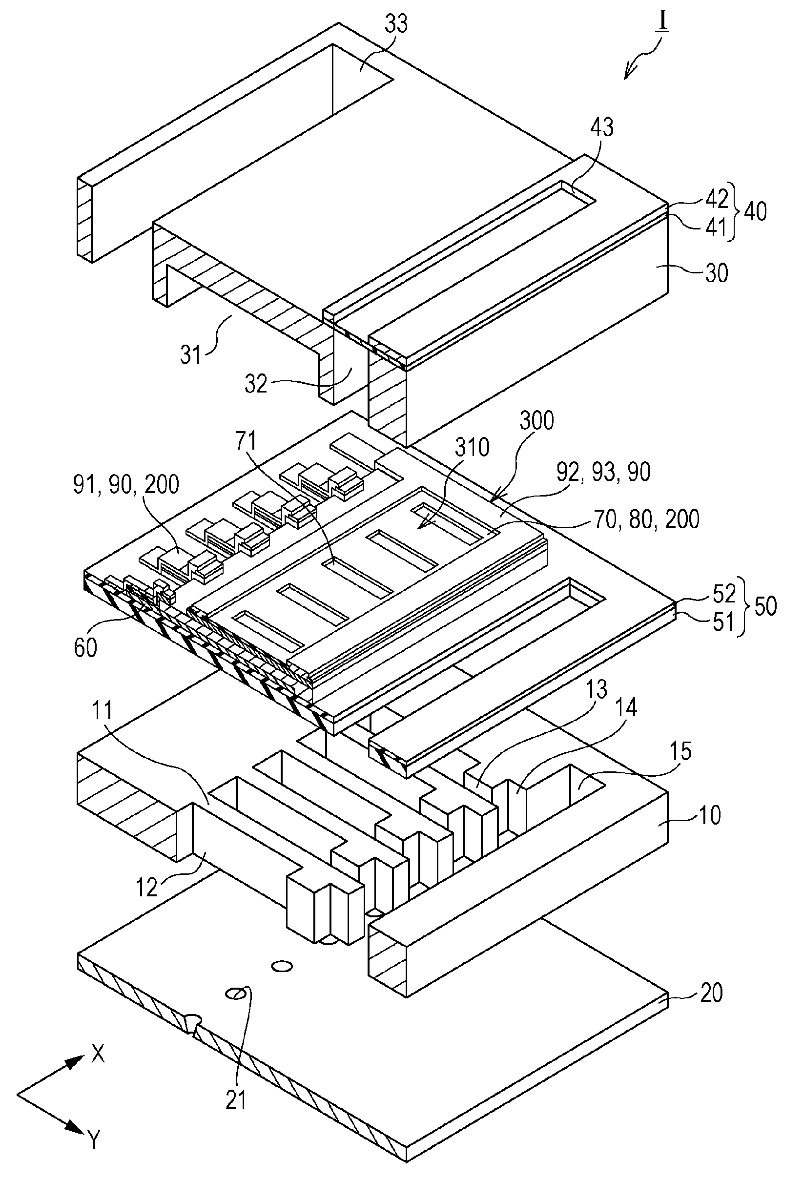
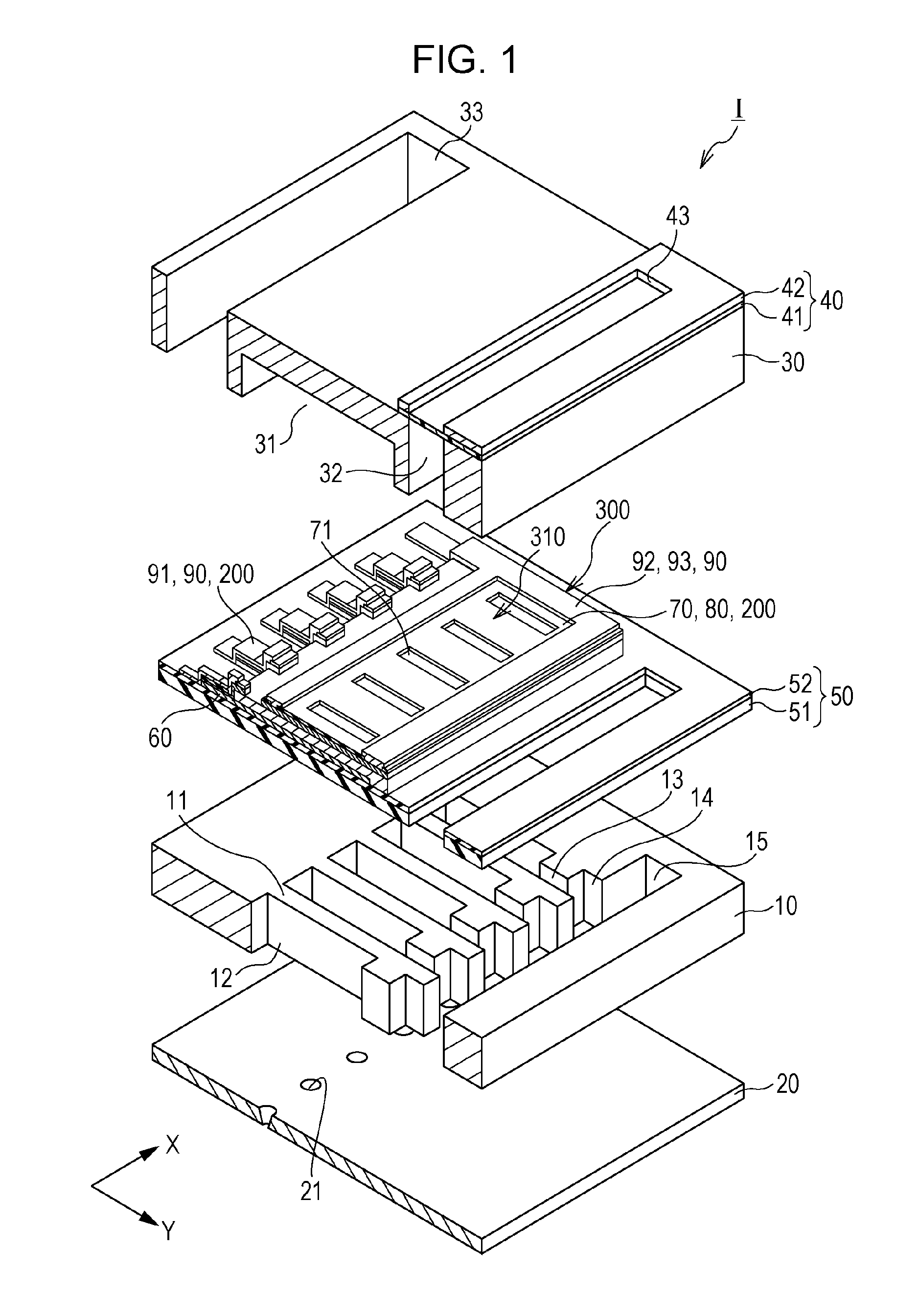
[0038]FIG. 1 is a perspective view of an ink jet recording head as an example of a liquid ejecting head according to Embodiment 1 of the invention. FIG. 2 is a plan view of the flow channel substrate used in the recording head. FIG. 3A is a cross-sectional view taken along line IIIA-IIIA in FIG. 2, and FIG. 3B is an enlarged view of FIG. 3A. FIG. 4 is a cross-sectional view taken along line IV-IV in FIG. 2.

[0039]As illustrated in these drawings, the ink jet recording head I, an example of a liquid ejecting head according to this embodiment, has a flow channel substrate 10 that has pressure chambers 12. Defined by several walls 11, the pressure chambers 12 are arranged in the direction of the arrangement of several nozzle openings 21 for ejecting ink of the same color. This direction is hereinafter referred to as the direction of arrangement of the pressure chambers 12 or first direction X. The direction perpendicular to first direction X is hereinafter referred to as second directio...

embodiment 2

[0109]FIG. 10A is an enlarged cross-sectional view of some essential components of an ink jet recording head as an example of a liquid ejecting head according to Embodiment 2 of the invention, and FIG. 10B is a cross-sectional view of the same recording head taken along line XB-XB. Features similar to those described in Embodiment 1 are represented by the same reference numerals as in that embodiment and are not described in the following.

[0110]As illustrated in these drawings, an ink jet recording head I according to this embodiment has piezoelectric elements 300 in which the first electrode 60 extends over several active sections 310 and serves as a common electrode for them, while the second electrode 80 provides separate electrodes for the active sections 310.

[0111]More specifically, the first electrode 60 is narrower than the width of the pressure chamber 12 in second direction Y and continuously extends in first direction X.

[0112]The piezoelectric layer 70 extends beyond the e...


PUM

PropertyMeasurementUnit
temperatureaaaaaaaaaa
liquid ejectingaaaaaaaaaa
pressureaaaaaaaaaa

Abstract

A flow channel substrate has pressure chambers, and the pressure chambers communicate with nozzle openings for ejecting liquid. Each of piezoelectric elements on the flow channel substrate has a piezoelectric layer, a pair of electrodes, and a wiring layer coupled to the electrodes. The wiring layer has an adhesion layer and a conductive layer on the adhesion layer. The adhesion layer contains at least one selected from nickel, chromium, titanium, and tungsten. The piezoelectric element has an insulating film at least between the wiring layer and the electrodes. The wiring layer and the electrodes of the piezoelectric element are coupled via contact holes created through the insulating film.

Description

BACKGROUND[0001]1. Technical Field[0002]The present invention relates to a liquid ejecting head that ejects liquid through nozzle openings, a liquid ejecting apparatus that has a liquid ejecting head, a piezoelectric element for liquid ejecting heads or similar devices, and a method for manufacturing a piezoelectric element.[0003]2. Related Art[0004]A known liquid ejecting head ejects droplets of liquid through its nozzle openings by deforming piezoelectric elements (piezoelectric actuators) to change the pressure in the liquid in pressure chambers that communicate with the nozzle openings. A representative example of a liquid ejecting head is an ink jet recording head, which ejects droplets of ink.[0005]A typical ink jet recording head has a flow channel substrate, and also has pressure chambers and piezoelectric elements on either side of the flow channel substrate. The pressure chambers communicate with nozzle openings. The piezoelectric elements operate to deform diaphragms and ...

Claims


Application Information

Patent Timeline
Patent Type & Authority Applications(United States)
IPC IPC(8): B41J2/14H01L41/22H01L41/047
CPCB41J2/14233Y10T29/42B41J2002/14241B41J2002/14491B41J2202/03B41J2202/18B41J2002/14362B41J2/161B41J2/1629B41J2/1634B41J2/1642B41J2/1646B41J2/1643B41J2/1623B41J2/1645B41J2/1628B41J2/1631B41J2/1632H10N30/877H10N30/875H10N30/2047H10N30/06H10N30/074H10N30/082B41J2/14201H10N30/87
Inventor HIRAI, EIJUKIMURA, SAYAKA
Owner SEIKO EPSON CORP
Why Eureka
Try Eureka