Method for manufacturing polymeric piezoelectric film and polymeric piezoelectric film

Active Publication Date: 2010-03-18
KUREHA KAGAKU KOGYO KK
View PDF7 Cites 16 Cited by
  • Summary
  • Abstract
  • Description
  • Claims
  • Application Information

AI Technical Summary

Benefits of technology

[0005]In view of the above-mentioned situation, a principal object of the present invention is to provide a method for stably producing a polymer piezoelectri

Problems solved by technology

However, in the production methods of Patent documents 1 and 2, it has been difficult to stably control the neck stretching.
If a first consideration is made on the case of polarization using non-contact electrodes, such as a pair of needle electrode rows principally disclosed in Patent documents 1 and 2, the heating condition for a crystalline polymer sheet moved at a prescribed speed (while the case of batch treatmen

Method used


Image

  • Method for manufacturing polymeric piezoelectric film and polymeric piezoelectric film
  • Method for manufacturing polymeric piezoelectric film and polymeric piezoelectric film
  • Method for manufacturing polymeric piezoelectric film and polymeric piezoelectric film

Examples


Example

Comparative Example 1

[0053]A 160 μm-thick sheet of PVDF having an inherent viscosity (η i) of 1.2 dl / g (polyvinylidene fluoride: made by Kureha Kagaku Kogyo K. K.) was supplied to a device having an organization substantially as shown in FIG. 1 and subjected to a neck stretching-polarization concurrent processing. More specifically, the above PVDF sheet was moved over a hard chrome mirror-finished heating roller 12 (with a surface roughness Ra13 spaced apart from the roller 12 by ca. 10 mm and disposed at a density of 2 electrodes / cm2 was increase form 0 kV to 9 kV to effect a neck stretching-polarization concurrent processing.

[0054]At the initial period when the applied voltage was 0 kV, neck stretching was stably performed on the roller 12 surface, and a stretched film of ca. 40 μm in thickness and ca. 300 mm in width was obtained. However, when 9 kV was applied, it changed into a state where a non-linear neck line NL′ was formed by gradual bellow-like elongation of the central po...

Example

Comparative Example 2

[0056]A neck stretching-polarization concurrent processing of a 160 μm-thick PVDF sheet was performed in the same manner as in Comparative Example 1 except for using a hard chrome mirror-finished roller (Ra<0.03 μm) of 200 mm in diameter as the heating roller.

[0057]In the course of gradually increasing the voltage applied between the roller and the needle electrodes up to 10 kV, the neck line moved downwards and became non-linear until the breakage of the stretched film at the time of application of 10 kV, so that a long period of production was impossible.

[0058]With respect to the portion supplied with 10 kV before the breakage, thickness irregularities were noticeable with eyes, and a relatively good portion (of ca. 1 m in length) exhibited d31=27 pC / N (and a dispersion peak temperature≧120° C.) but side portions outside the relatively good portion included a portion exhibiting only d31≦1 pC / N.

Example

Example 1

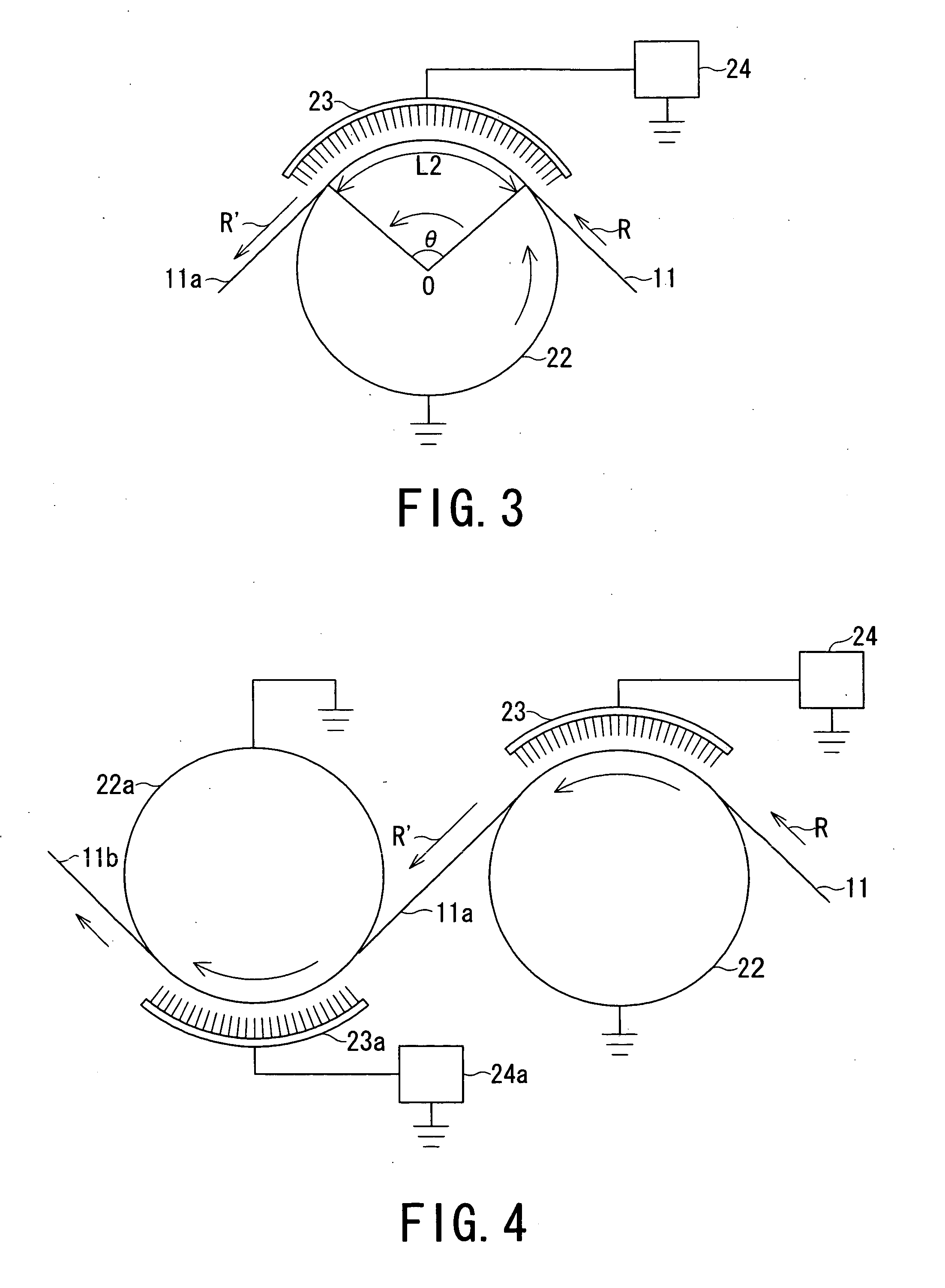
[0059]A neck stretching-polarization concurrent processing of a 160 μm-thick PVDF sheet was performed in the same manner as in Comparative Example 2 except for using a heating roller (corresponding to one denoted by 22 in FIG. 3) formed by uniformly applying a lubricant comprising polytetrafluoroethylene fine particles in the form of an aerosol for spraying (“DAIFRE GA6010”, made by Daikin Kogyo K. K.) onto the surface of a hard chrome mirror-finished roller used in Comparative Example 2.

[0060]The processing could be continued until the voltage applied between the roller(22) and the needle electrodes (23) was increased up to 12 kV. Under this condition, a linear neck line NL was formed sufficiently within the roller-sheet contact length L2 (=ca. 70 mm) while some up-and-down fluctuation of the neck line was observed

[0061]The processing was continued until ca. 20 m of a piezoelectric film was produced, when the instability of neck line (i.e., non-linear formation and deviati...


PUM

PropertyMeasurementUnit
Angleaaaaaaaaaa
Diameteraaaaaaaaaa
Lengthaaaaaaaaaa

Abstract

A method for producing a polymer piezoelectric film, comprising: a process of moving and stretching a crystalline polar polymer sheet in contact with a conductive stretching roller having a diameter of at least 30 mm and a surface friction coefficient which has been reduced to such a level as to allow a relative displacement of the crystalline polar polymer sheet in contact with the conductive stretching roller: and a step in the process of applying a polarization voltage between an electrode disposed opposite to the crystalline polar polymer sheet and the conductive stretching roller to polarize the crystalline polar polymer sheet. As a result, it is possible to stably produce a polymer piezoelectric film exhibiting stable piezoelectricity over a large area. Especially, it is possible to obtain polymer piezoelectric film exhibiting a temperature-dispersion peak temperature of d31 piezoelectricity coefficient at least 120° C. and surface scratches extending in one direction.

Description

TECHNICAL FIELD[0001]The present invention relates to a method for stably producing a polymer piezoelectric film having a stably large piezoelectricity (and pyroelectricity), and a polymer piezoelectric film thus formed.BACKGROUND ART[0002]As a typical method for producing a high-performance piezoelectric film as represented by a large piezoelectricity (usually developing also pyroelectricity as is well known), there is known a type of method, comprising: polarizing a crystalline polymer sheet of, e.g., a polyvinylidene fluoride resin by corona discharge from a pair of electrodes, at least one of which comprises a needle electrode, disposed opposite to each other so as to place the crystalline polymer sheet therebetween, while stretching the crystalline polymer sheet (Patent documents 1 and 2). Incidentally, the terms “sheet” and “film” are used herein so that the former refers to a state before stretching and the latter refers to a state after stretching, regardless of a convention...

Claims


Application Information

Patent Timeline
IPC IPC(8): H04R17/00B32B3/00H01L41/08H01L41/193H01L41/22H01L41/257H01L41/45
CPCH01L41/257H01L41/45Y10T29/49162Y10T428/24471Y10T29/42C08F114/22H10N30/045H10N30/098
Inventor MORIYAMA, NOBUHIRONAKAMURA, KEN'ICHISUZUKI, KAZUYUKISUZUKI, KEITAROU
Owner KUREHA KAGAKU KOGYO KK
Why Eureka
Try Eureka