Piezoelectric substance, piezoelectric element, and liquid discharge head and liquid discharge apparatus using piezoelectric element

a piezoelectric element and piezoelectric technology, applied in the direction of piezoelectric/electrostrictive device details, device details, device material selection, etc., can solve the problems of high piezoelectricity that is originally expected to not be achieved, and achieve high piezoelectricity that is originally expected to not be achieved, and achieves uniform and high discharge performance. , the effect of large piezoelectricity

Inactive Publication Date: 2009-11-05
CANON KK
View PDF19 Cites 5 Cited by
  • Summary
  • Abstract
  • Description
  • Claims
  • Application Information

AI Technical Summary

Benefits of technology

[0018]The piezoelectric substance of the present invention is a piezoelectric substance which is made of oxide which is made of ABO3, where a principal component of A is Pb, and principal components of B contain at least two kinds of elements among Nb, Mg, Zn, Sc, Cd, Ni, Mn, Co, Yb, In, and Fe, and Ti, and is formed as a uniaxial orientation crystal or a single crystal which has a-domains and c-domains of tetragonal. By using this piezoelectric substance, a piezoelectric element using a piezoelectric substance (piezoelectric film) which has large piezoelectricity can be obtained. Furthermore, by using this piezoelectric substance, a liquid discharge head which shows uniform and high discharging performance, and can perform patterning of a liquid with more various characteristics in further higher resolution on a processed surface can be obtained.

Problems solved by technology

Nevertheless, even if it is the above-mentioned piezoelectric highly piezoelectric material, when a piezoelectric film is formed by a thin film forming method using it, such high piezoelectricity that is originally expected has not been achieved yet.
Nevertheless, since a MPB region with good characteristics cannot be used in the above-mentioned method, such high piezoelectricity that is originally expected has not been achieved yet.

Method used


Image

  • Piezoelectric substance, piezoelectric element, and liquid discharge head and liquid discharge apparatus using piezoelectric element
  • Piezoelectric substance, piezoelectric element, and liquid discharge head and liquid discharge apparatus using piezoelectric element
  • Piezoelectric substance, piezoelectric element, and liquid discharge head and liquid discharge apparatus using piezoelectric element

Examples


embodiments

[0119]Hereafter, the piezoelectric element of the present invention and the liquid discharge head using this, and its production method will be described with citing examples.

example 1

[0120]Production sequence of a piezoelectric thin-film element of a first example is as follows.

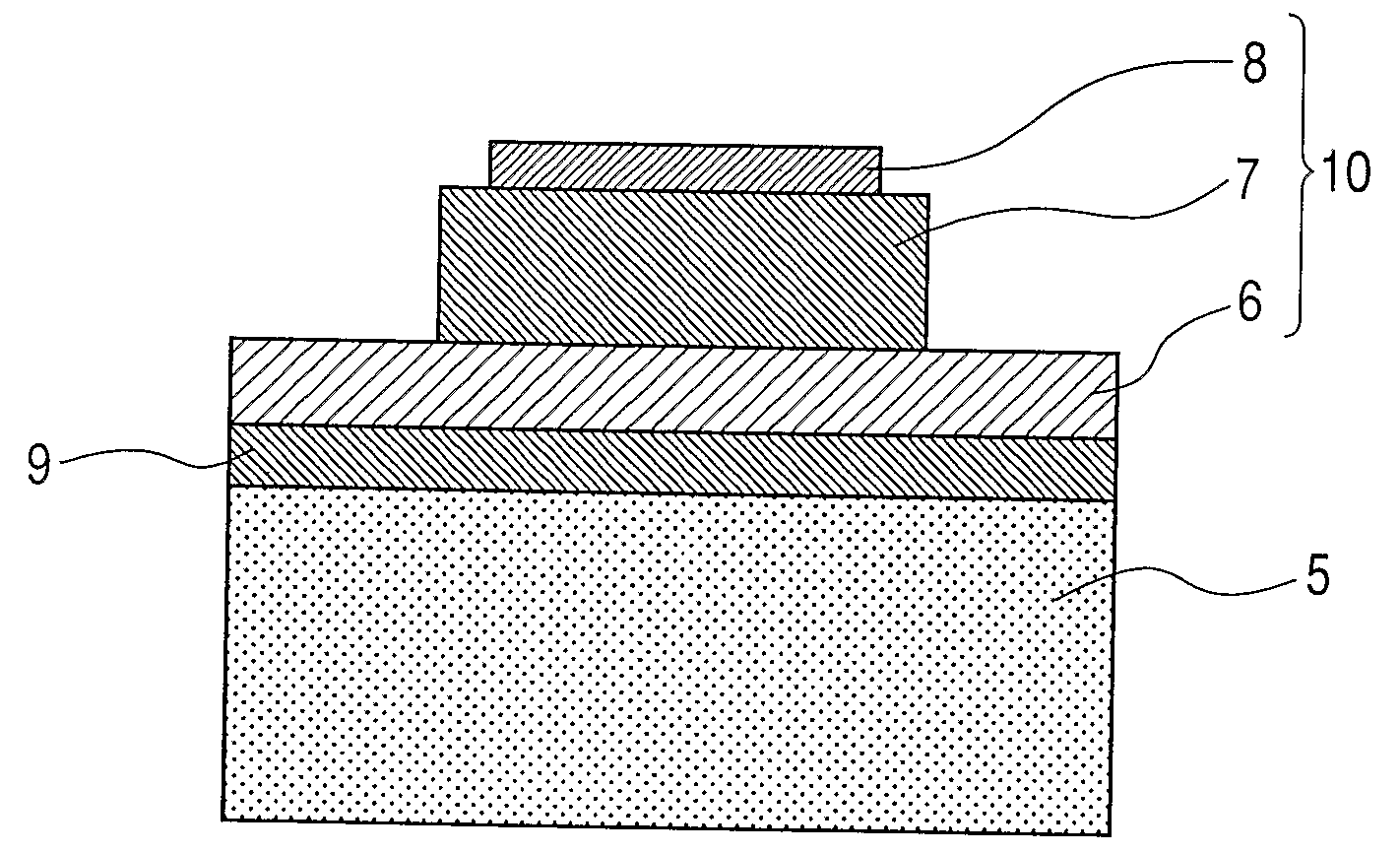
[0121]After performing hydrofluoric acid processing of a Si {100} substrate surface, a 100-nm-thick Y-doped ZrO2 film was formed at a substrate temperature of 800° C. by the sputtering method, and then, a 60-nm-thick CeO2 film was formed at a substrate temperature of 800° C. Both were single crystal films with orientation. Further, a 100-nm-thick LaNiO3 (LNO) film was formed on this at a substrate temperature of 850° C. as a lower electrode film by the sputtering method. Furthermore, a 200-nm-thick SrRuO3 (SRO) film was formed at a substrate temperature of 600° C. on this LNO film, and the substrate which had a lower electrode film and the like was obtained. The electrode film and SRO film were single crystal films of orientation.

[0122]PMN-PT with 3.3 μm of film thickness was formed as a film as a piezoelectric film on the above-mentioned lower electrode / buffer layer / substrate by an RF ...

example 2

[0124]Production sequence of a piezoelectric thin-film element of a second example is as follows.

[0125]After performing hydrofluoric acid processing of a Si {100} substrate surface, a 100-nm-thick Y-doped ZrO2 film was formed at a substrate temperature of 800° C. by the sputtering method, and then, a 60-nm-thick CeO2 film was formed at a substrate temperature of 800° C. Both were single crystal films of orientation. Further, a 100-nm-thick LaNiO3 (LNO) film was formed on this at a substrate temperature of 850° C. as a lower electrode film by the sputtering method. Furthermore, a 200-nm-thick SrRuO3 (SRO) film was formed at a substrate temperature of 600° C. on this LNO film, and the substrate which had a lower electrode film and the like was obtained. The electrode film and SRO film were single crystal films of orientation.

[0126]Lead scandium niobate-lead titanate with 4.2 μm of film thickness was formed as a film as a piezoelectric film on the above-mentioned lower electrode / buff...


PUM

PropertyMeasurementUnit
thicknessaaaaaaaaaa
thicknessaaaaaaaaaa
thicknessaaaaaaaaaa

Abstract

A piezoelectric substance which is made of oxide with perovskite type structure which is made of ABO3, where a principal component of A is Pb, and principal components of B contain at least two kinds of elements among Nb, Mg, Zn, Sc, Cd, Ni, Mn, Co, Yb, In, and Fe, and Ti, characterized by being a uniaxial orientation crystal or a single crystal which has an a-domain and a c-domain of tetragonal.

Description

TECHNICAL FIELD[0001]The present invention relates to a piezoelectric substance, a piezoelectric element, and a liquid discharge head and liquid discharge apparatus using the piezoelectric element.BACKGROUND ART[0002]In recent years, a piezo-electric actuator attracts attention in a portable information device field, and chemistry and medical fields as a new motor, which replaces an electromagnetic motor, in that miniaturization and high densification of a motor are allowed. The piezoelectric actuator does not generate an electromagnetic noise on the occasion of its drive, and, is not influenced by noise. Furthermore, the piezoelectric actuator attracts attention as a part of making such equipment with submillimeter class size that is represented by a micromachine, and a minute piezoelectric thin-film element is requested as its drive source.[0003]As for a piezoelectric material used for a piezoelectric element, generally, it is common to obtain by finely forming a sintered compact ...

Claims


Application Information

Patent Timeline
Patent Type & Authority Applications(United States)
IPC IPC(8): H01L41/04H01L41/18B32B15/00B41J2/045B41J2/055B41J2/135B41J2/14B41J2/16C04B35/472H01L41/09H01L41/187H01L41/22H01L41/29H01L41/316
CPCH01L41/0973B41J2/161H01L41/316B41J2202/03H01L41/1875B41J2/1646H10N30/1051H10N30/2047H10N30/8548H10N30/076C04B35/46B41J2/16H10N30/853
Inventor IFUKU, TOSHIHIROTAKEDA, KENICHIFUKUI, TETSUROFUNAKUBO, HIROSHI
Owner CANON KK
Why Eureka
Try Eureka