Method for manufacturing a polymeric piezoelectric film

a piezoelectric film and polymer technology, applied in the direction of electric/magnetic/electromagnetic heating, variable capacitors, transportation and packaging, etc., can solve the problems of difficult to form a necking portion, difficult to stably control the neck stretching, and difficult to form a polymer piezoelectric film, etc., to achieve stable piezoelectric performance, stable production, and large piezoelectricity

Active Publication Date: 2013-01-22
KUREHA KAGAKU KOGYO KK
View PDF15 Cites 1 Cited by
  • Summary
  • Abstract
  • Description
  • Claims
  • Application Information

AI Technical Summary

Benefits of technology

[0005]In view of the above-mentioned situation, a principal object of the present invention is to provide a method for stably producing a polymer piezoelectric film having a stably large piezoelectricity over a large area, and a polymer piezoelectric film thus formed and exhibiting stable piezoelectric performances.
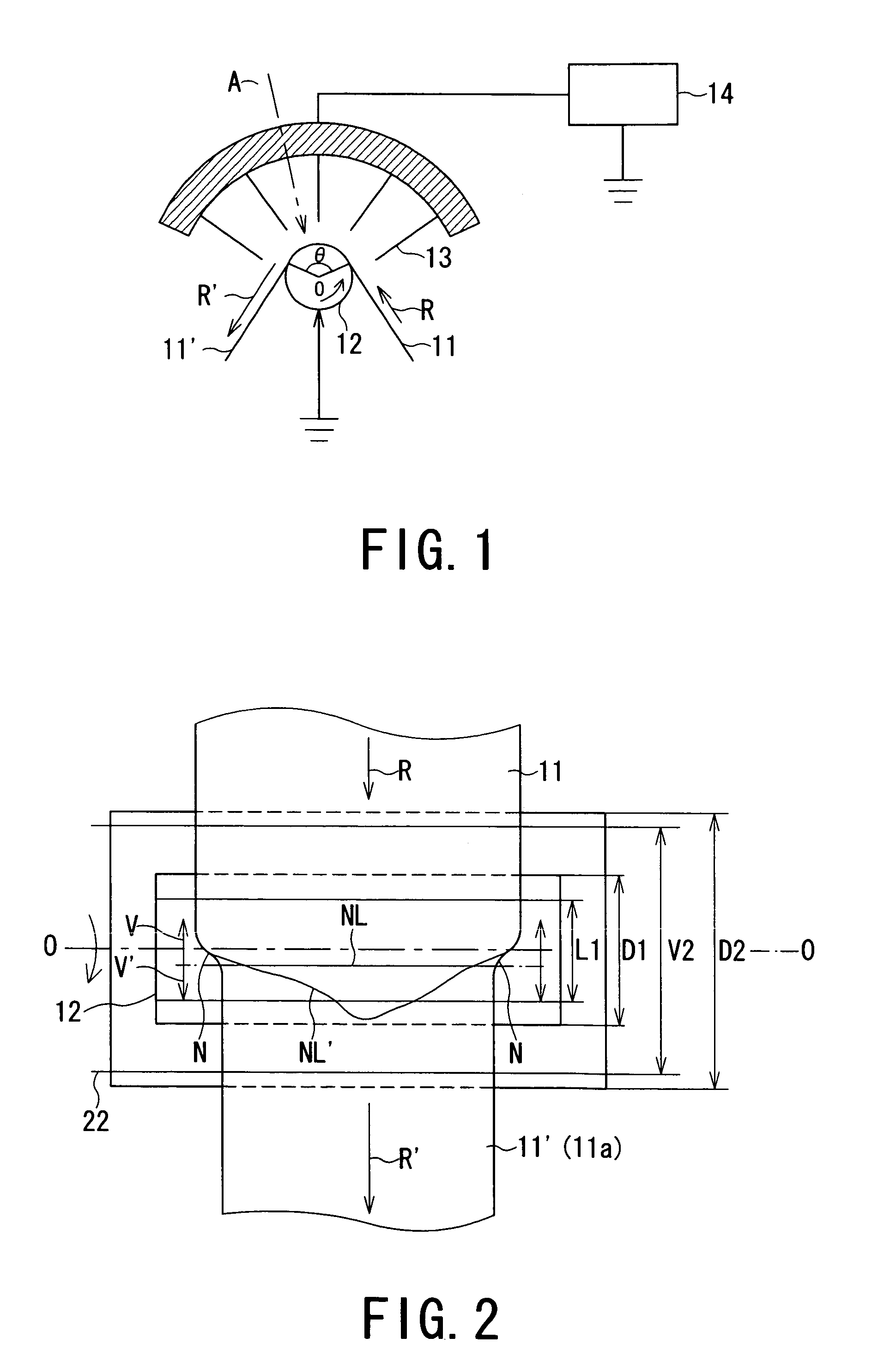
[0013]On the other hand, the present inventors have acquired the following knowledge. Even a roller having a large diameter D2 can be used as a stretching roller contacting the neck stretching portion of a thin polymer piezoelectric stock sheet while obviating the breakage of the sheet if its surface friction coefficient has been reduced to such a level as to allow a relative displacement of the polymer piezoelectric stock sheet in contact with the roller instead of mirror surface-finished rollers generally used in plastic sheet transportation and used as small-diameter roller (D1) or large-diameter roller (D2) in the above examples. Further, by using such an improved large-diameter roller, among the above-mentioned non-ideal neck stretching phenomena, (i) the movement of neck line position still remains but can be sufficiently stably retained within the range of contact length L2 with the roller, and (ii) the formation of a non-linear neck line NL′ can be remarkably suppressed to stably obtain a substantially linear neck line NL, whereby commercial production of a polymer piezoelectric film stably exhibiting a high-degree of piezoelectricity has become possible.
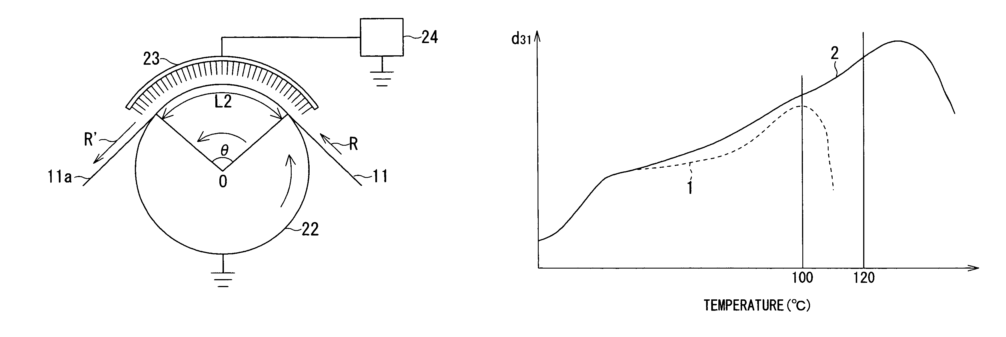
[0015]Further, a characteristic of the polymer piezoelectric film obtained by the polarization (stretching-polarization concurrent processing) by the DC (direct-current) high-voltage application at the neck stretching portion adopted by the method for producing the polymer piezoelectric film of the present invention, is that it has a remarkably improved thermal resistance of piezoelectricity (represented by, e.g., a piezoelectricity coefficient in the stretching direction (i.e., d31 piezoelectricity coefficient)), compared with a polymer piezoelectric film obtained through conventional stretching→polarization sequential processing. For example, compared with a temperature-dispersion peak temperature of d31 piezoelectricity coefficient of ca. 100° C. obtained through conventional stretching→polarization sequential processing, a value of at least 120° C. can be obtained. This means that the polymer piezoelectric film can withstand heating up to 120° C. and can retain its piezoelectricity even thereafter. Particularly, in the case of using a surface-roughened conductive stretching roller according to a preferred embodiment of the production method according to the present invention, the resultant piezoelectric film is provided with surface scratches extending in one direction, as a result of contact with the roller through neck stretching accompanied with relative movement with the roller.

Problems solved by technology

However, in the production methods of Patent documents 1 and 2, it has been difficult to stably control the neck stretching.
If a first consideration is made on the case of polarization using non-contact electrodes, such as a pair of needle electrode rows principally disclosed in Patent documents 1 and 2, the heating condition for a crystalline polymer sheet moved at a prescribed speed (while the case of batch treatment is set aside) cannot be made uniform because of thickness irregularity or other causes present in the sheet, thus making it difficult to form a necking portion, so that it becomes difficult to form a polymer piezoelectric film having a stable piezoelectricity over a large area.
Further, the sheet or film during the stretching is liable to be sucked to touch one side of needle electrodes, thus causing breakage thereof.

Method used


Image

  • Method for manufacturing a polymeric piezoelectric film
  • Method for manufacturing a polymeric piezoelectric film
  • Method for manufacturing a polymeric piezoelectric film

Examples


example 1

[0059]A neck stretching-polarization concurrent processing of a 160 μm-thick PVDF sheet was performed in the same manner as in Comparative Example 2 except for using a heating roller (corresponding to one denoted by 22 in FIG. 3) formed by uniformly applying a lubricant comprising polytetrafluoroethylene fine particles in the form of an aerosol for spraying (“DAIFRE GA6010”, made by Daikin Kogyo K. K.) onto the surface of a hard chrome mirror-finished roller used in Comparative Example 2.

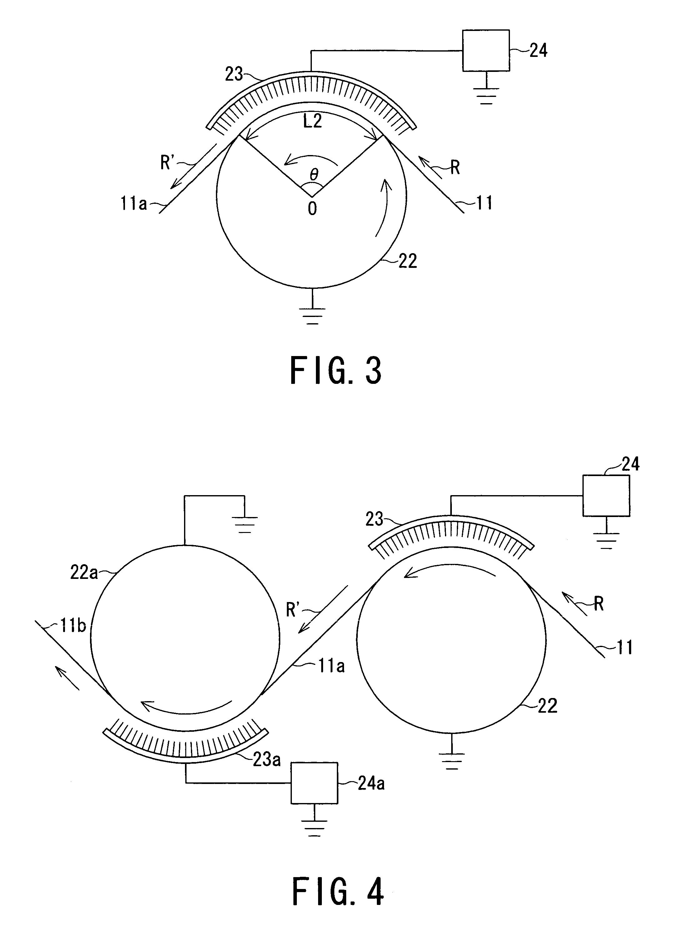
[0060]The processing could be continued until the voltage applied between the roller(22) and the needle electrodes (23) was increased up to 12 kV. Under this condition, a linear neck line NL was formed sufficiently within the roller-sheet contact length L2 (=ca. 70 mm) while some up-and-down fluctuation of the neck line was observed

[0061]The processing was continued until ca. 20 m of a piezoelectric film was produced, when the instability of neck line (i.e., non-linear formation and deviation out of...

example 2

[0063]A neck stretching-polarization concurrent processing of a 160 μm-thick PVDF sheet was performed in the same manner as in Example 1 except for using a heating roller (of surface roughness Ra=1 μm; corresponding to one denoted by 22 in FIG. 3) formed by abrading the surface of a hard chrome mirror-finished roller used in Comparative Example 2, successively with sandpaper (of # 40) and sandpaper (of # 240).

[0064]Under the voltage application condition of 12 kV between the roller(22) and the needle electrodes (23), a stable production of a piezoelectric film under a stable neck stretching state was possible while some fluctuation of a linear neck line within the contact length L2 region was observed, and the stable production state was maintained even after production of 100 m of piezoelectric film.

[0065]The thus-obtained piezoelectric film exhibited a piezoelectricity coefficient d31=30 pC / N (and a dispersion peak temperature≧120° C.) over the full width, and no irregularity in p...

example 3

[0066]A neck stretching-polarization concurrent processing of a 160 μm-thick PVDF sheet was performed in the same manner as in Example 2 except for using a heating roller (22) of 200 mm in outer diameter surfaced with a titanium oxide-based ceramic layer (of surface roughness Ra=1 μm and a resistance between the roller axis and the surface=77 ohm).

[0067]Under the voltage application condition of 12 kV between the roller(22) and the needle electrodes (23), a stable production of a piezoelectric film under a stable neck stretching state was possible while some fluctuation of a linear neck line within the contact length L2 region was observed, and the stable production state was maintained even after production of 200 m of piezoelectric film.

[0068]The thus-obtained film exhibited a piezoelectricity coefficient d31=30 pC / N (and a dispersion peak temperature≧120° C.) over the full width, and no irregularity in piezoelectricity coefficient or thickness was observed.


PUM

PropertyMeasurementUnit
diameteraaaaaaaaaa
central angleaaaaaaaaaa
surface roughness coefficientaaaaaaaaaa

Abstract

A method for producing a polymer piezoelectric film, comprising: a process of moving and stretching a crystalline polar polymer sheet in contact with a conductive stretching roller having a diameter of at least 30 mm and a surface friction coefficient which has been reduced to such a level as to allow a relative displacement of the crystalline polar polymer sheet in contact with the conductive stretching roller: and a step in the process of applying a polarization voltage between an electrode disposed opposite to the crystalline polar polymer sheet and the conductive stretching roller to polarize the crystalline polar polymer sheet. As a result, it is possible to stably produce a polymer piezoelectric film exhibiting stable piezoelectricity over a large area. Especially, it is possible to obtain polymer piezoelectric film exhibiting a temperature-dispersion peak temperature of d31 piezoelectricity coefficient at least 120° C. and surface scratches extending in one direction.

Description

TECHNICAL FIELD[0001]The present invention relates to a method for stably producing a polymer piezoelectric film having a stably large piezoelectricity (and pyroelectricity), and a polymer piezoelectric film thus formed.BACKGROUND ART[0002]As a typical method for producing a high-performance piezoelectric film as represented by a large piezoelectricity (usually developing also pyroelectricity as is well known), there is known a type of method, comprising: polarizing a crystalline polymer sheet of, e.g., a polyvinylidene fluoride resin by corona discharge from a pair of electrodes, at least one of which comprises a needle electrode, disposed opposite to each other so as to place the crystalline polymer sheet therebetween, while stretching the crystalline polymer sheet (Patent documents 1 and 2). Incidentally, the terms “sheet” and “film” are used herein so that the former refers to a state before stretching and the latter refers to a state after stretching, regardless of a convention...

Claims


Application Information

Patent Timeline
Patent Type & Authority Patents(United States)
IPC IPC(8): H04R17/10H01L41/107H01L41/08H01L41/193H01L41/22H01L41/257H01L41/45
CPCH01L41/257H01L41/45C08F114/22Y10T29/49162Y10T428/24471Y10T29/42H10N30/045H10N30/098
Inventor MORIYAMA, NOBUHIRONAKAMURA, KEN'ICHISUZUKI, KAZUYUKISUZUKI, KEITAROU
Owner KUREHA KAGAKU KOGYO KK
Why Eureka
Try Eureka