Method and apparatus for detecting object

a detection method and object technology, applied in the field of image processing, can solve the problem that the fusion cannot be applied to a real scene in real time, and achieve the effect of accurately detecting eliminating or reducing the effect of shielding

Inactive Publication Date: 2014-06-26
RICOH KK
View PDF6 Cites 27 Cited by
  • Summary
  • Abstract
  • Description
  • Claims
  • Application Information

AI Technical Summary

Benefits of technology

[0013]It is one of objects of the present invention to provide a method and an apparatus for detecting an objet that has strong robustness for the object shielding and can accurately detect objects as much as possible.
[0016]According to the method and the apparatus for detecting the object, the effect of the shielding can be eliminated or reduced, and objects can be accurately detected as much as possible.

Problems solved by technology

In scenes of a plurality of stereo cameras such as binocular cameras, the data amount of transmission over the network and the data amount of processing for fusing the original data sets, namely the fusion of pixel sets, is large, and the fusion cannot be applied to a real scene in real time.

Method used


Image

  • Method and apparatus for detecting object
  • Method and apparatus for detecting object
  • Method and apparatus for detecting object

Examples


first embodiment

[0044]In the following, a whole process of detecting the object by a plurality of stereo cameras according to an embodiment of the present invention is described.

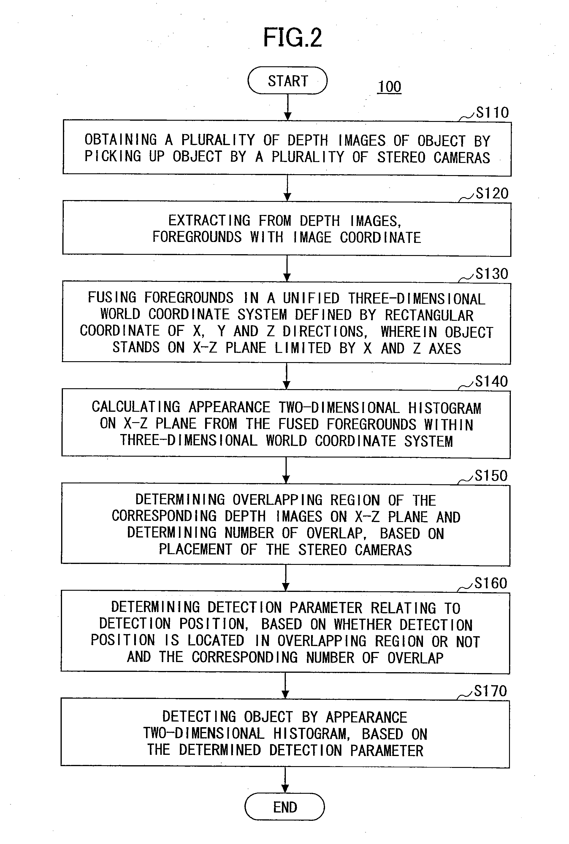
[0045]FIG. 2 is an overall flowchart illustrating the method for detecting the object 100 according to an embodiment of the present invention.

[0046]For convenience of explanation, with regard to the overall flowchart, supposing that a plurality of stereo cameras are placed in a predetermined space, on an object that appears in the predetermined space has stereo imaging performed, and the object is detected by processing the stereo image.

[0047]The “predetermined space” may be a room, such as a supermarket or a factory building, may also be an outdoor space, such as a school field or a military field, the predetermined space may be any space as long as it can be a monitoring object. The object for detecting is not limited, and it may be a person, an animal, a flying object, a car or a chair.

[0048]The “stereo camera” means a c...

second embodiment

[0123]The object detection performed by the appearance two-dimensional histogram is described above; however, the object detection may also be performed by combining a height two-dimensional histogram, and the meaning and the obtainment method of the height two-dimensional histogram will be described below.

[0124]FIG. 10 is an overall flowchart illustrating the method for detecting the object 200 according to the second embodiment of the present invention.

[0125]The method for detecting the object 200 according to the second embodiment of the present invention illustrated in FIG. 10, performs the object detection by using both the appearance two-dimensional histogram and the height two-dimensional histogram.

[0126]The object detection method of the second embodiment 200 illustrated in FIG. 10, is different from the object detection method of the first embodiment 100 in step S240 and steps S280 and S290 which are added. Other steps S210-S230 and S250-S270 are similar to corresponding st...

third embodiment

[0149]As described above, the height of an object is not affected by the number and the placement of stereo cameras, therefore, an object tracking can be performed by using a height two-dimensional histogram.

[0150]FIG. 13 is a flowchart illustrating a method for tracking the object by using the two-dimensional histogram 300 according to an embodiment of the present invention.

[0151]As illustrated in FIG. 13, in step S310, a height two-dimensional histogram on the x-z plane is calculated from the foreground fused in the three-dimensional world coordinate system, by getting statistics of the height of a foreground point with a maximum height within the foreground points in the vertical members so as to obtain the height two-dimensional histogram representing the maximum heights within the vertical members. In this case, it is supposed that a foreground fused in a unified three-dimensional world coordinate system has been obtained, and the obtainment method may refer to steps S110-S130 ...


PUM


Abstract

A method and an apparatus for detecting an object are disclosed. The method comprises the steps of obtaining a plurality of depth images of the object; extracting foregrounds; fusing the foregrounds in a unified three-dimensional world coordinate system; calculating an appearance two-dimensional histogram from the fused foreground by the following steps of dividing the foreground into vertical members and getting statistics of the numbers of foreground points in the vertical members so as to obtain the appearance two-dimensional histogram; determining an overlapping region and the number of overlaps based on the placement of stereo cameras; determining a detection parameter relating to a detection position based on the overlapping region and the number of overlaps; and detecting the object by the appearance two-dimensional histogram based on the determined detection parameter.

Description

BACKGROUND OF THE INVENTION[0001]1. Field of the Invention[0002]The present invention generally relates to image processing, and specifically, a method and an apparatus for detecting an object based on stereo vision.[0003]2. Description of the Related Art[0004]A technology for detecting an object by using images collected by a stereo camera, such as patent document U.S. Pat. No. 8,009,871B for which the title of the invention is “METHOD AND SYSTEM TO SEGMENT DEPTH IMAGES AND TO DETECT SHAPES IN THREE-DIMENSIONALLY ACQUIRED DATA”, patent document U.S. Pat. No. 5,202,928A for which the title of the invention is “SURFACE GENERATION METHOD FROM BOUNDARIES OF STEREO IMAGES”, and an article “Stereo Person Tracking with Adaptive Plan-View Templates of Height and Occupancy Statistics” published by Michael Harville in 2003, has existed.[0005]As an example of positioning or detection of a person, person positioning is the base of the technology for humans, and a service can be provided or pus...

Claims


Application Information

Patent Timeline
Patent Type & Authority Applications(United States)
IPC IPC(8): G06T7/20G06T7/00
CPCG06T7/0081G06T7/208G06T7/2086G06T2207/10021G06T2207/10028G06T2207/20144G06T7/204G06T2207/30232G06T2207/30241G06T7/0044G06T7/0075G06T7/0097G06T7/2033G06T2207/30196G06T7/11G06T7/174G06T7/194G06T7/248G06T7/277G06T7/285G06T7/593G06T7/74
Inventor FAN, SHENGYINWANG, XIN
Owner RICOH KK
Why Eureka
Try Eureka