Decorative piece produced by setting on amorphous metal

a technology of amorphous metal and decorative elements, applied in the direction of decorative arts, thin material processing, ornamental structures, etc., can solve the problems of not being able to guarantee the retention of stones 100%, the current method of setting aesthetic elements cannot be used, etc., to achieve the effect of improving the retention of at least one aesthetic elemen

Active Publication Date: 2014-06-26
OMEGA SA
View PDF11 Cites 11 Cited by
  • Summary
  • Abstract
  • Description
  • Claims
  • Application Information

AI Technical Summary

Benefits of technology

[0054]In another advantageous embodiment, said at least one aesthetic element comprises at least one throat into which said first material is inserted in order to improve the retention of said at least one aesthetic element.
[0055]Another advantage of this solution is that it makes it possible to set any type of material. In fact, the principle employed is a principle of set-in material, i.e. that a substrate in a deformable material is introduced into a plastically non-deformable material so as to allow setting and to give the illusion that it is this plastically non-deformable material which is set.

Problems solved by technology

Nevertheless, a disadvantage of this method is that it is limited to supports produced in ductile metals or ductile metallic alloys.
Consequently, it is no longer possible to use the current method for setting aesthetic elements such as for example precious stones.
The disadvantage of glueing is not guaranteeing 100% retention of the stones because, in contrast to setting, this technique does not involve mechanical retention of the stones.
. . ), the retention of the bonding over the long term is made difficult.
Consequently, retention of the stones is not guaranteed, which is not acceptable for quality products.

Method used


Image

  • Decorative piece produced by setting on amorphous metal
  • Decorative piece produced by setting on amorphous metal
  • Decorative piece produced by setting on amorphous metal

Examples


first embodiment

[0091]A first embodiment is used in the case where the amorphous alloys accommodate permanent deformation and have elastic limits which are not too high, typically less than 1,500 MPa: the setting method is identical to that used for crystalline metals, i.e. cold plastic deformation of the beads 9 produced in the amorphous alloy.

second embodiment

[0092]A second embodiment is used in the case where the amorphous alloys have elastic limits which are too high for cold plastic deformation, typically greater than 1,500 MPa: the setting method consists of heating the beads 9 to a temperature greater than the glass transition temperature Tg of the amorphous metallic alloy in order to reduce greatly the viscosity and therefore the force necessary for deformation thereof. Once the beads 9 are at the right temperature, they are deformed so that the setting can take place. A cooling operation is then effected in order to solidify them and to make it possible to make the setting definitive. This solution has the advantage of allowing an intimate contact between the amorphous metallic alloy and the aesthetic element 3, which improves retention of the latter. In fact, in the case of cold plastic deformation, as much for crystalline metals as amorphous ones, elastic resilience operates during release of the force applied on the bead 9. Thi...

third embodiment

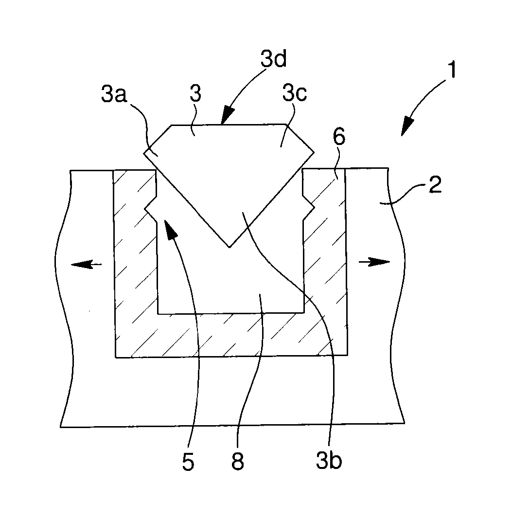
[0093]A third embodiment is used when the amorphous alloys are difficult to set by cold or hot plastic deformation. This embodiment consists of making use of the high elastic deformation of amorphous alloys, typically 2%, in contrast to crystalline alloys which deform plastically from 0.5%. The method consists of pressing the aesthetic element 3 into the setting hole of the substrate 6. Under pressure, the amorphous metallic alloy of the substrate 6 deforms elastically making it possible for the aesthetic element 3 to be inserted. When the catching means 5, in the shape of a setting recess, and the girdle or end or the edge 3a of the aesthetic elements 3 are situated one opposite the other, an elastic resilience operates. The elastic resilience of the catching means 5 on the aesthetic element 3 makes it possible to retain the latter definitively, as can be seen in FIGS. 15 and 16.


PUM

PropertyMeasurementUnit
distanceaaaaaaaaaa
breaking elongationaaaaaaaaaa

Abstract

The present invention relates to a decorative piece comprising a support produced in a material which does not include plastic deformation and in which at least one hollow is provided, characterised in that said hollow being filled with a first material being an at least partially amorphous alloy forming a substrate in which at least one housing is provided, said at least one housing being designed so that at least one aesthetic element can be housed therein.

Description

[0001]This application claims priority from European Patent Application No. 13165604.3 filed Apr. 26, 2013 and European Patent Application No. 12199276.2 filed Dec. 21, 2012, the entire disclosure of which is hereby incorporated by reference herein by reference.[0002]The present invention relates to a decorative piece. This decorative piece comprises a support into which at least one aesthetic element is set.TECHNOLOGICAL BACKGROUND[0003]There are known, in prior art, decorative pieces which are intended to be set into a wearable object, such as a watch or jewellery, and which consist of setting of an aesthetic element on the parts of said wearable object acting as support.[0004]For this purpose, the support is produced in a metallic alloy and is machined so that housings appear. During this machining, catching means having the shape of hooks are produced. In general, these hooks are produced with the material forming the wearable object, i.e. in a monobloc fashion with the object. ...

Claims


Application Information

Patent Timeline
Patent Type & Authority Applications(United States)
IPC IPC(8): A44C17/02A44C17/04
CPCA44C17/005A44C17/04Y10T29/23Y10T428/22A44C17/00A44C27/00B44C1/00
Inventor LAUPER, STEPHANEKISSLING, GREGORYWINKLER, YVESDUBACH, ALBANBOURBAN, STEWESNETUSCHILL, ALEXANDREBLASER, LIONEL
Owner OMEGA SA
Why Eureka
Try Eureka