Needleless connector

a technology of connectors and needles, applied in the field of medial devices, can solve the problems of affecting the possibility of needlestick injury to medical personnel, and the exposure of medical personnel to infection, so as to reduce the cost of medical treatment, improve the stability of the liquid guide, and improve the stability of the structur

Inactive Publication Date: 2014-06-26
PACIFIC HOSPITAL SUPPLY
View PDF3 Cites 21 Cited by
  • Summary
  • Abstract
  • Description
  • Claims
  • Application Information

AI Technical Summary

Benefits of technology

[0011]First, the spring which could suffer elastic fatigue caused by force exertion only carries out the function of automatically replacing the stop member during which the first annular portion and the second annular portion of the stop member block the channel to fulfill the function of closing the needleless connector to prevent the outside air from leaking into the connector or to prevent the liquid medicine and blood in the patient from flowing reversely. Therefore, even though the spring suffers elastic fatigue after long service, the closing capability of the stop member is still not affected. As a result, the needleless connector of the present invention can have excellent structure stability and closing capability.
[0012]Second, the needle of prior art is not required and instead the mutual connection of the needleless injector and the needleless connector is used during blood transfusion or liquid medicine delivery. That further avoids the needlestick injury, replacement and recycling of needles to reduce medical costs.
[0013]Third, during the sliding of the stop member in the first channel, the second annular portion formed by the external perimeter of the stop member has been disposed against the se

Problems solved by technology

The needle of the syringe is a sharp structure and therefore, it is possible for the medical personnel to suffer needlestick injury when they use the syringe carelessly.
If the needle is contaminated, the medical personnel will be exposed to infection.
As a result, the used needles are not allowed to be arbitrarily discarded and they need to be recycled and treated professionally to reduce the possibilities of personnel's infection and environmental contamination in order to improve the safety of operation, which

Method used


Image

  • Needleless connector
  • Needleless connector
  • Needleless connector

Examples


Embodiment Construction

[0022]The detailed description and technology of the present invention will be described as follows with figures and description. However, the accompanying figures are provided only for explanation, but not for limiting the present invention.

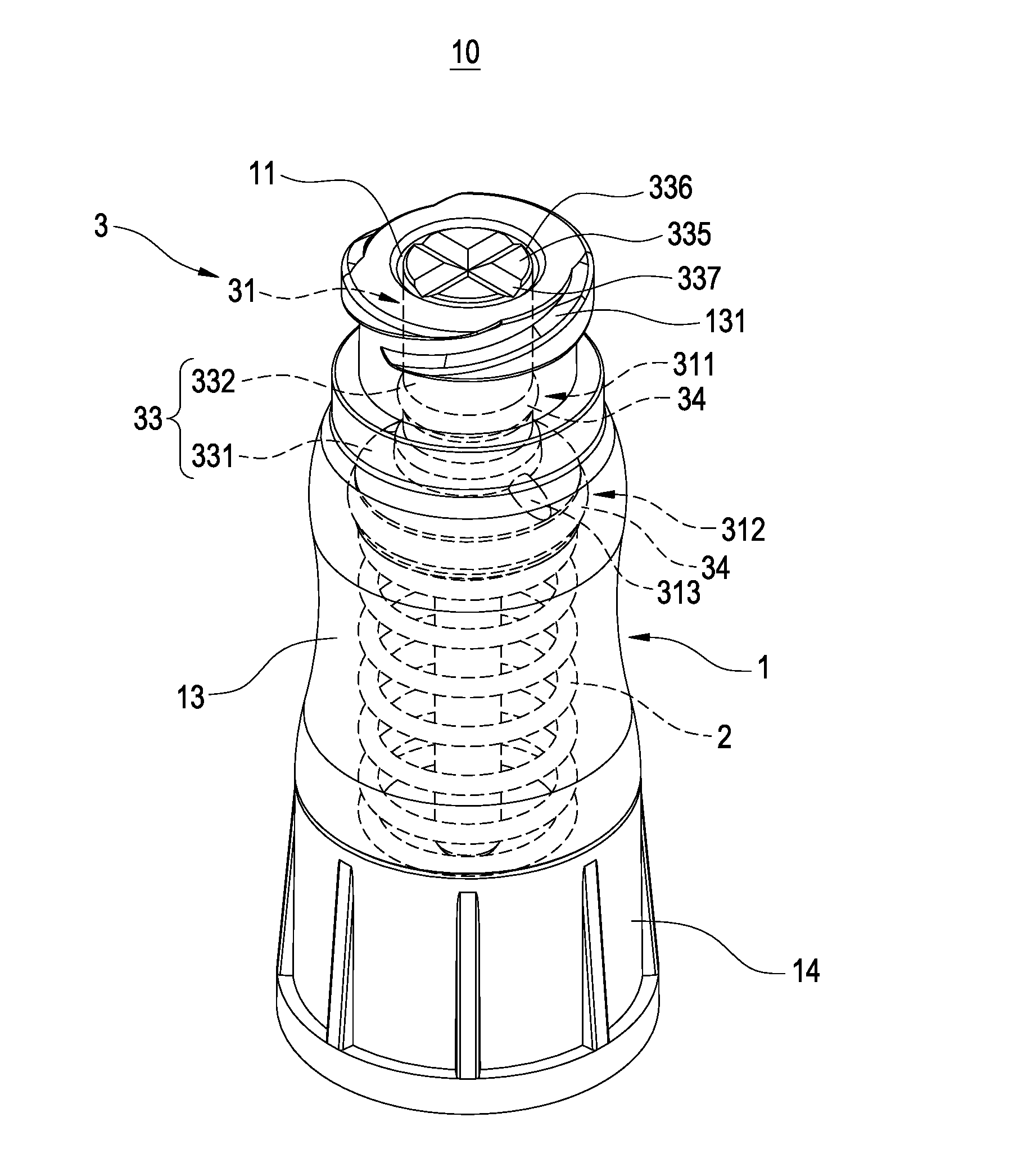
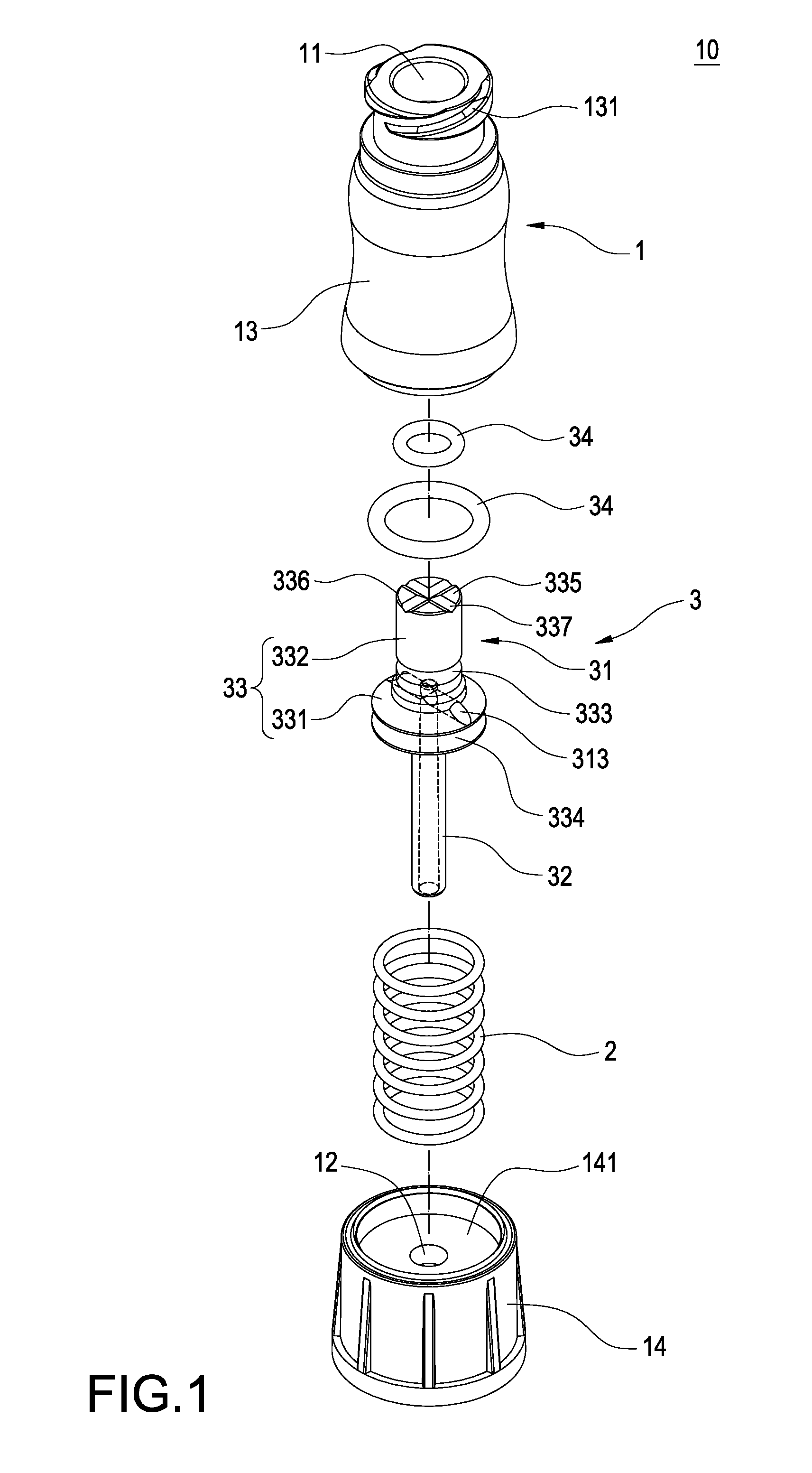
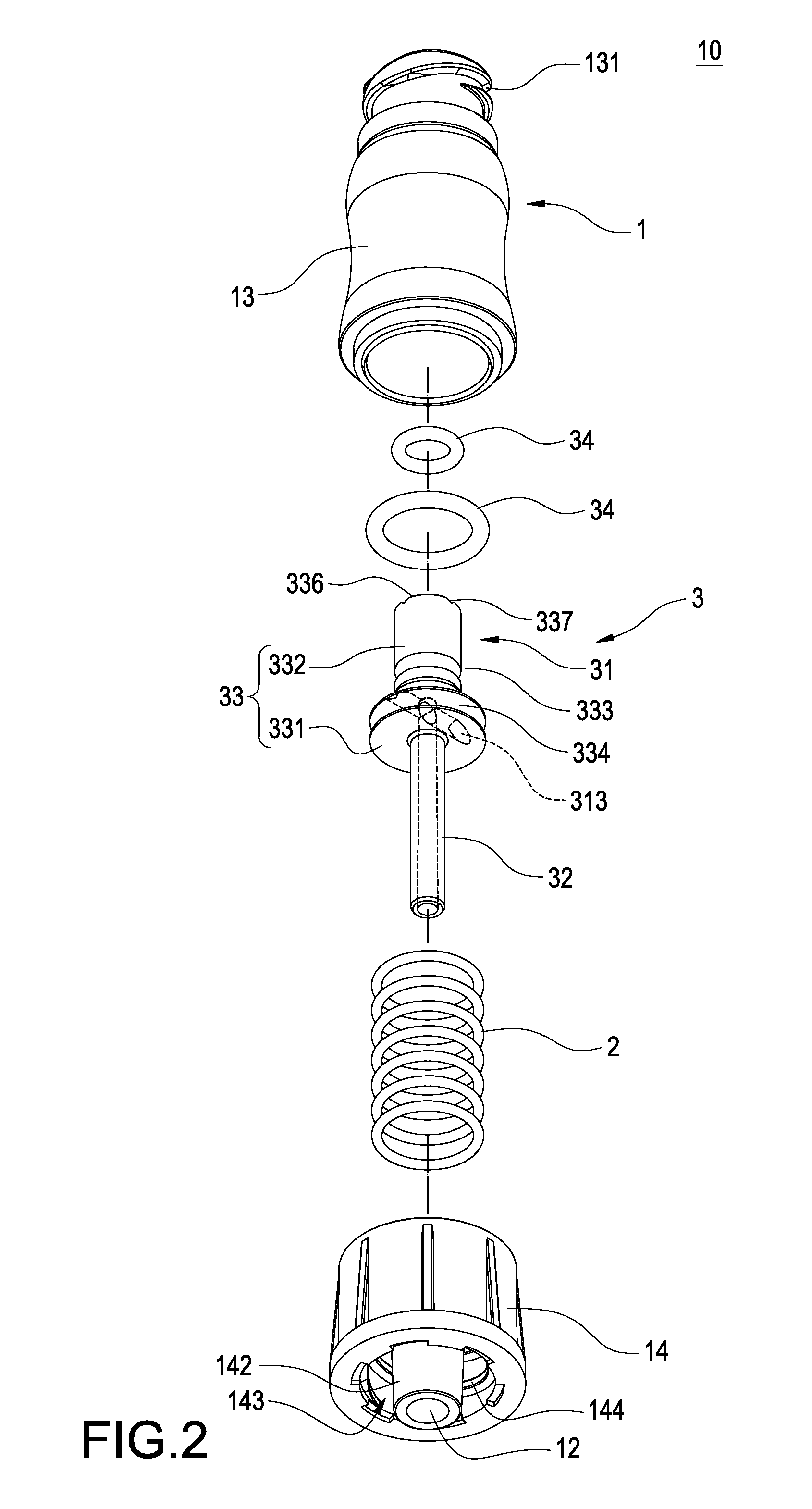
[0023]Please refer to FIGS. 1-4, in which the present invention is to provide a needleless connector 10 mainly comprising a hollow connector 1, a spring 2, and a switch assembly 3.

[0024]The hollow connector 1 has a first channel 11 and a second channel 12 connected to each other at both ends. The perimeter of the first channel 11 extends inward to have an annular block 111. The inner perimeter of the annular block 111 forms a first annular wall 112. A second annular wall 113 is formed between the annular block 111 and the second channel 12 in the first channel 11. The size of the perimeter of the first annular wall 112 is smaller than that of the second annular wall 113.

[0025]The detailed description is given below. The hollow connector 1 compri...


PUM


Abstract

A needleless connector includes a hollow connector, a spring, and a switch assembly. The inner perimeter of the hollow connector forms a first annular wall and a second annular wall. The spring is disposed in the hollow connector. The switch assembly has a stop member and a guide tube connected to the stop member, the stop member being pressed between the annular block and the spring, the guide tube being disposed in the hollow connector, the external perimeter of the stop member forming a first annular portion against the first annular wall and a second annular portion against the second annular wall, a groove being disposed between the first annular portion and the second annular portion of the stop member, the groove being connected to the guide tube. Thus, the integral structure stability and good closing performance are achieved such that the outside air cannot leak into the connector structure.

Description

BACKGROUND OF THE INVENTION[0001]1. Field of the Invention[0002]The present invention relates to a medial device for blood transfusion or liquid medicine delivery, more particularly to a needleless connector.[0003]2. Description of Prior Art[0004]A conventional syringe is commonly used as the device for medicine injection. The needle of the syringe is a sharp structure and therefore, it is possible for the medical personnel to suffer needlestick injury when they use the syringe carelessly. If the needle is contaminated, the medical personnel will be exposed to infection. As a result, the used needles are not allowed to be arbitrarily discarded and they need to be recycled and treated professionally to reduce the possibilities of personnel's infection and environmental contamination in order to improve the safety of operation, which in contrast increases the medical cost. Therefore, needleless connectors are currently available in the market and are used for medical injection with ne...

Claims


Application Information

Patent Timeline
IPC IPC(8): A61M39/10
CPCA61M39/10A61M2039/2486A61M2039/263
Inventor HO, SHIH-CHICHEN, MING-CHUNG
Owner PACIFIC HOSPITAL SUPPLY
Why Eureka
Try Eureka